shifter kart II

Status
Not open for further replies.

Ognib

bingo spelled backwards
Messages
151
Reaction score
0
Location
kc
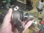
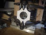
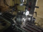
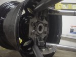
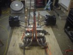
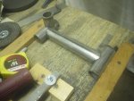
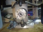
The backing plate is still long & the corners don't yet fit in between the tube ends, so the upper arm is off of level.
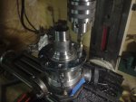
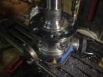
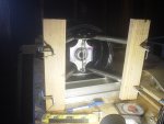
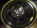
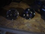
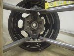
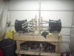
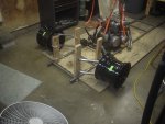
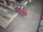
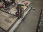
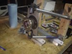
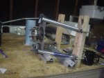
Mock ups give a visual "feel" as to how it's coming together.
 

Attachments

  • chassis91.JPG
    chassis91.JPG
    873.3 KB · Views: 8
  • chassis92.JPG
    chassis92.JPG
    854.2 KB · Views: 9
  • chassis93.JPG
    chassis93.JPG
    864.1 KB · Views: 9

Ognib

bingo spelled backwards
Messages
151
Reaction score
0
Location
kc
Cut some plugs off of a piece of bar stock.
These are for the ball joint bosses.
Need a couple of v blocks for set up on the mill, to hold them securely.
Will be facing the ends & squaring to the sides before drilling & boring the taper to match the ball joint studs.
Toolmakers vice pulls the jaw down while clamping...this eliminates the dreaded "jaw lift", helping to maintain an accurate setup.
 

Attachments

  • chassis94.JPG
    chassis94.JPG
    877.8 KB · Views: 6
  • chassis95.JPG
    chassis95.JPG
    884.7 KB · Views: 6

Ognib

bingo spelled backwards
Messages
151
Reaction score
0
Location
kc
This setup worked well.
 

Attachments

  • chassis96.JPG
    chassis96.JPG
    900.1 KB · Views: 6

Ognib

bingo spelled backwards
Messages
151
Reaction score
0
Location
kc
Got a new face mill cutter...much quicker than using a 1/2" end mill for this type work.
Leaves a visable pattern on the steel, but the feel is that of polished metal.
 

Attachments

  • chassis97.JPG
    chassis97.JPG
    902.4 KB · Views: 6

Ognib

bingo spelled backwards
Messages
151
Reaction score
0
Location
kc
Boring ball joint stud tapers today.
Found an old guy about my age that has a small one man grind shop.
He mfgs machine cutting tools & sharpens drill & mill bits.
Took him a fresh 3/4", 4 flute end mill along with my measurements & he tapered it to my specs.

Fits perfect...:cheers2:
 

Attachments

  • chassis102.JPG
    chassis102.JPG
    833 KB · Views: 7
  • chassis101.JPG
    chassis101.JPG
    820 KB · Views: 7
  • chassis100.JPG
    chassis100.JPG
    809.9 KB · Views: 7
  • chassis99.JPG
    chassis99.JPG
    870.3 KB · Views: 6
  • chassis98.JPG
    chassis98.JPG
    711.1 KB · Views: 8

Ognib

bingo spelled backwards
Messages
151
Reaction score
0
Location
kc
Start fitting the ball joint bosses to the backing plates.
But first, a massive cleanup.
 

Attachments

  • chassis104.JPG
    chassis104.JPG
    830.6 KB · Views: 7
  • chassis103.JPG
    chassis103.JPG
    913 KB · Views: 9

Ognib

bingo spelled backwards
Messages
151
Reaction score
0
Location
kc
With a couple of the now completed bosses in place, I'm still using the paper template for verifying dimensions.

Straps will act as stiffeners, helping to eliminate flex at the tips of the plate.
Angles will keep the two ends in good alignment while assembling, as well as keeping side straps square with the plate during the process.
Slider gauge, used from side to side will assure that it's all centered on the plate.
 

Attachments

  • chassis108.JPG
    chassis108.JPG
    850.1 KB · Views: 11
  • chassis107.JPG
    chassis107.JPG
    878.7 KB · Views: 11
  • chassis106.JPG
    chassis106.JPG
    797.2 KB · Views: 11
  • chassis105.JPG
    chassis105.JPG
    843.3 KB · Views: 10

Ognib

bingo spelled backwards
Messages
151
Reaction score
0
Location
kc
My hubs are 5 lug...my wheels are 4X4".
Put the hubs in the press & pushed it all apart in preparation for re-drilling.

I bought all of the parts cheaply enough that I was cool with the work involved in changing the lug pattern...I've got more time than money these days.

Get the caliper out & do some measuring & draw up a layout.
Then set up the rotary table on the mill & see what I can come up with. :cheers2:
 

Attachments

  • chassis109.JPG
    chassis109.JPG
    808.9 KB · Views: 8
  • chassis110.JPG
    chassis110.JPG
    722.9 KB · Views: 9

Ognib

bingo spelled backwards
Messages
151
Reaction score
0
Location
kc
Thanks, giving it my best shot.

The rotary table & chuck were full of chips wet with cutting oil from previous work.
Broke it all down & cleaned it up for this work.

Measured the flange & drew a plan to scale.
Did the layout work & checked it...perfect 4" span for center of the stud holes.
It appears that I will be able to use one of the existing holes as the line drops right into their centers.
 

Attachments

  • chassis115.JPG
    chassis115.JPG
    852.8 KB · Views: 7
  • chassis114.JPG
    chassis114.JPG
    812.7 KB · Views: 7
  • chassis113.JPG
    chassis113.JPG
    744.1 KB · Views: 6
  • chassis112.JPG
    chassis112.JPG
    906.7 KB · Views: 7
  • chassis111.JPG
    chassis111.JPG
    906.8 KB · Views: 5

Ognib

bingo spelled backwards
Messages
151
Reaction score
0
Location
kc
Setting up the rotary table for re drilling the lug bolt pattern.

My rough setup is using a countersink...I put a drop of layout dye on the edges & lower the bit into the hole & rotate it backwards by hand... adjusting the x/y axis on the table until it wipes the dye off cleanly.

Then I set the indicator & rotate it from side to side & front to back... adjusting the table x/y until I get a consistent reading all around.
At this point my setup is within a half a thou of being centered with the spindle centerline.

Then the chuck goes on top of that & the same procedure is employed.

The goal is that when the flange is mounted & centered for drilling, the drill bit will be on my layout line consistently as I rotate the setup from one drilling position to the next.

Slow going for me as I've only been doing machine work for about 2 1/2 yrs & I have a tendency to keep going back & re checking my work. :cheers2::cheers2:
 

Attachments

  • chassis116.JPG
    chassis116.JPG
    854.8 KB · Views: 6
  • chassis117.JPG
    chassis117.JPG
    861.4 KB · Views: 6
  • chassis118.JPG
    chassis118.JPG
    868.2 KB · Views: 6

Ognib

bingo spelled backwards
Messages
151
Reaction score
0
Location
kc
Got the first hub drilled. Couple of the holes are close to the originals but my guesstimate is that the car they came off of probably weighed 3,000 lb ish. I'm tracking the weight of my tubing, engine & components & I'm figuring the buggy will be in the 500-600 lb range, dry, before fluids & driver. Should be plenty good.

Fresh grease on the bearings & get the studs in & everything pressed back together & can get the hub bolted to a wheel.
That will hold the hub in position for a more accurate fit up to the ball joints.

Progress! :cheers2:
 

Attachments

  • chassis119.JPG
    chassis119.JPG
    864.4 KB · Views: 7
  • chassis120.JPG
    chassis120.JPG
    863.4 KB · Views: 7

Ognib

bingo spelled backwards
Messages
151
Reaction score
0
Location
kc
5 to 4. Result of several days work. Fits good. Happy with the results.

Now that everything's solidly mocked up I can finalize my dimensions . I can already see that the upper & lower control arms are needing to be a bit closer together...don't want them rubbing against the wheel edge during suspension travel.

Sorry about the poor lighting...my fluorescent bank back here quit. Need to get a new ballast.
 

Attachments

  • chassis124.JPG
    chassis124.JPG
    863.9 KB · Views: 9
  • chassis123.JPG
    chassis123.JPG
    854.6 KB · Views: 8
  • chassis122.JPG
    chassis122.JPG
    841.1 KB · Views: 8
  • chassis121.JPG
    chassis121.JPG
    821.4 KB · Views: 8

Ognib

bingo spelled backwards
Messages
151
Reaction score
0
Location
kc
Control arms, spindles ready to go on the frame.
 

Attachments

  • chassis131.JPG
    chassis131.JPG
    861.4 KB · Views: 3
  • chassis132.JPG
    chassis132.JPG
    851 KB · Views: 5
  • chassis137.JPG
    chassis137.JPG
    751.3 KB · Views: 4

Ognib

bingo spelled backwards
Messages
151
Reaction score
0
Location
kc
Mock ups inspire me.
 

Attachments

  • chassis139.JPG
    chassis139.JPG
    864.7 KB · Views: 5
  • chassis138.JPG
    chassis138.JPG
    863.4 KB · Views: 4

5814SpeedCo

Member
Messages
150
Reaction score
8
Location
Fort Worth, TX
Mock ups inspire me.

What are you going to be using as a differential for the independent rear suspension?

Also what hubs did you use to begin with? I'm getting ready to tackle a kart using an 1980 xs850 triple engine but will have to do some work on the middle drive to covert it from shaft to chain. Probably will cost me around $100 to do. 79hp and 50ft-lb of torque, should make for a fun little machine
 

Attachments

  • Screenshot_20190410-152256.jpg
    Screenshot_20190410-152256.jpg
    275.1 KB · Views: 0

Ognib

bingo spelled backwards
Messages
151
Reaction score
0
Location
kc
What are you going to be using as a differential for the independent rear suspension?

Also what hubs did you use to begin with? I'm getting ready to tackle a kart using an 1980 xs850 triple engine but will have to do some work on the middle drive to covert it from shaft to chain. Probably will cost me around $100 to do. 79hp and 50ft-lb of torque, should make for a fun little machine


Rear drive components are all Subaru, dif, hubs, etc. I bought the entire cradle out of an 95 Legacy, I think it was.
Did quite a bit of research before I bought. Seems like they are pretty popular with guys who are doing this.
Pull the dif out of the original case & fab a "can" to hold it & replace the ring gear with the drive sprocket. Easier said than done, I'm sure, but I figure if they can do it so can I.

My engine is rated at 84hp on the bike tag info. Not sure about the torque.
I'm figuring it should make a pretty snappy ride. I'm calculating that mine will only weight around 600lb. That's a fair wt to hp ratio.
 

Ognib

bingo spelled backwards
Messages
151
Reaction score
0
Location
kc
Progress.
 

Attachments

  • chassis168.JPG
    chassis168.JPG
    861.1 KB · Views: 3
  • chassis170.JPG
    chassis170.JPG
    856.2 KB · Views: 3
  • chassis174.JPG
    chassis174.JPG
    866.8 KB · Views: 4
  • chassis177.JPG
    chassis177.JPG
    872 KB · Views: 4
Status
Not open for further replies.
Top