shifter kart II

Status
Not open for further replies.

Ognib

bingo spelled backwards
Messages
151
Reaction score
0
Location
kc
Greetings all!

Been a busy winter. A lot of 9-5 work & a project cutting some brass parts on the mill for a friend.

Finally have some time for this project.
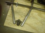
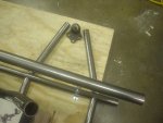
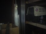
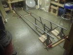
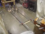
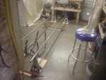
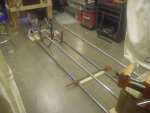
Ordered 80' of tubing...1.250 x .109 mild. Picking it up tomorrow.
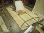
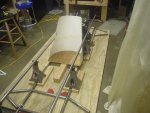
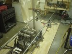
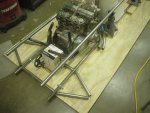
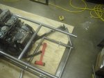
Beginning on the frame & cage.
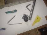
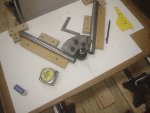
Also now have a chop saw to simplify keeping the cuts on square & for proper angles for bracing.

Should have an update & some pics / vid early next week.
Excited to get back to work on this. :cheers2:

Here's the link for the first segment thread on this build.

http://www.diygokarts.com/vb/showthread.php?t=36462
 

Ognib

bingo spelled backwards
Messages
151
Reaction score
0
Location
kc
Previous cuts were done with either reciprocating saw or cut off wheel on angle grinder. LOL

Thanks ez, gonna be a cool summer!
 

Ognib

bingo spelled backwards
Messages
151
Reaction score
0
Location
kc
A couple of quick shots.

Steel stacked in a corner.

Blocks & clamps hold the width of the bottom rails secure while I'm measuring to center & square the engine cradle for mounting in the frame.
My floor is level on both axis & flat, so going to start the structure there.

Been scrubbing down the engine a bit at a time.
 

Attachments

  • chassis1.JPG
    chassis1.JPG
    763.9 KB · Views: 15
  • chassis2.JPG
    chassis2.JPG
    801.9 KB · Views: 16
  • kaw1.JPG
    kaw1.JPG
    833.2 KB · Views: 17

Ognib

bingo spelled backwards
Messages
151
Reaction score
0
Location
kc
To all the dads out there, happy fathers day.

Some frame mock up today.
I have a couple of designs I'm considering.

The main objective is the challenge of creating a well built piece that handles & performs well.
Beyond that is a strong desire to have it manifest good proportion & pleasing visual balance...thu look, if you will.

The first concept is to lay the top rails in a wedge configuration.
Visually, this is my preference.

Second is to run the top rail parallel to the bottom rail.
It's main advantage, in my mind, is that it simplifies creating mounting points for the top control arm.
It's probably stronger in resisting torsional twist in the frame as well.
 

Attachments

  • chassis4.JPG
    chassis4.JPG
    839.9 KB · Views: 15
  • chassis5.JPG
    chassis5.JPG
    837.5 KB · Views: 11
  • chassis6.JPG
    chassis6.JPG
    812.1 KB · Views: 11
  • chassis7.JPG
    chassis7.JPG
    808.6 KB · Views: 11

Ognib

bingo spelled backwards
Messages
151
Reaction score
0
Location
kc
Greetings to all! :)

Straps hold the tubing snugly on the layout lines for accurate fit up on the build.

Gotta be square & on line if I expect it to track well & able to be tuned to a balanced disposition in accel, braking & cornering.

Rough control arm mock up allows me to approximate the rear axle centerline.
The principle of low polar moment of inertia which gives a quick & nimble response to steering input is achieved by having as much of the weight as possible between the axles, as low as possible in the chassis & as close to the center of mass as possible.
For this reason, I want to establish locations for both battery & fuel cell now for early integration into the design.
 

Attachments

  • chassis11.JPG
    chassis11.JPG
    826.1 KB · Views: 12
  • chassis10.JPG
    chassis10.JPG
    751.1 KB · Views: 12
  • chassis9.JPG
    chassis9.JPG
    785 KB · Views: 13
  • chassis8.JPG
    chassis8.JPG
    714.8 KB · Views: 12

Ognib

bingo spelled backwards
Messages
151
Reaction score
0
Location
kc
Got the patterns cut for a seat. Will be in aluminum.

Front & rear crossmembers fitted & blanks cut for the lower control arms.
 

Attachments

  • chassis27.JPG
    chassis27.JPG
    876.7 KB · Views: 12
  • chassis29.JPG
    chassis29.JPG
    861.7 KB · Views: 13

Ognib

bingo spelled backwards
Messages
151
Reaction score
0
Location
kc
All of my previous builds have been to existing frames...30's fords, tri 5 chebbys, late 60's F bodies, etc.

This is my first attempt at scratch building a tube frame & cage & it's an entirely different animal.
So I'm in a learning curve on developing my skills in the proper techniques & methods in a few areas.

When it comes to notching tubes for acceptable fit, it's a challenge to get good close tolerances for adequate structural integrity in the welds.

I tried the bi-metal hole saws from the hardware store...they're good for wood, plastics & soft metals like aluminum & brass...steel, not so good.


Found this vid that shows a good, quick technique for notching with a cut off saw & angle grinder.
Thought I'd share it for anyone here that may be contemplating a project in round tubing.

Cheers. :cheers2:

https://www.youtube.com/watch?v=mHBanmfn_CA
 

Ognib

bingo spelled backwards
Messages
151
Reaction score
0
Location
kc
Greetings to all. :cheers2:

My thoughts are consumed with this build, at this point.
This kinda stuff IS the "juice" for me!

Hung the carbs back on the engine...need everything in place to build to...or build around.
Small box approximates the size of a 1 gal fuel cell.
Piece of dowel, clamped to the ruler above the engine, is about where the top of the roll hoop will be to allow a few inches clearance above my helmet.

Looking for a small torsen limited slip differential. No luck on that yet.

Was talking to a guy last week & he was telling me that there may be a new drag strip coming to town.
We lost our previous facility, a few yrs back, due to rich folk who didn't like the noise & their political lackeys.
This is mucho good news, if true!!
 

Attachments

  • chassis35.JPG
    chassis35.JPG
    862.5 KB · Views: 13
  • chassis34.JPG
    chassis34.JPG
    847.1 KB · Views: 16
  • chassis33.JPG
    chassis33.JPG
    870.5 KB · Views: 14

Ognib

bingo spelled backwards
Messages
151
Reaction score
0
Location
kc
Went looking for small ball joints. Found these at the local o'reillys. Think they'll work ok.
Still looking for urethane bushings in proper dimensions for hanging things on the frame.
 

Attachments

  • chassis37.JPG
    chassis37.JPG
    830 KB · Views: 12
  • chassis38.JPG
    chassis38.JPG
    862.9 KB · Views: 10

SteelHorse

New member
Messages
37
Reaction score
0
Depending on the money you want to spend, Protodie has an amazing cradle and rear drivetrain setup.
 

Ognib

bingo spelled backwards
Messages
151
Reaction score
0
Location
kc
Thanks for the link. Much appreciated. Will check them out.

Contemplating widening the stance on my control arms. I know that there are ideal ratios for everything. That's a current subject of research.

I know that my track to wb ratio is 1.7ish to 1. Good for a quick response to steering input but not as prone to getting squirley as a 1.6 or so.
I would guess the 1.6 is probably about what they use on the sprint cars to make it easy to kick the rear end out in the corners. But with that quick response...they are a "handful" to drive.
Gotta have a big handful of cool nerve & skill to drive one hard & flat out!

Another bit of vid.
Mock ups become fit ups...

https://www.youtube.com/watch?v=qVe568lcVFo
 

SteelHorse

New member
Messages
37
Reaction score
0
Formula 1 is about 1.7. With a great suspension you should be able to handle
It just fine.
 

Ognib

bingo spelled backwards
Messages
151
Reaction score
0
Location
kc
One of my main references in the layout of the suspension is Carroll Smiths "tune to win."
He was the crew chief when the fords won at 24 hr lemans in the late 60's-early 70's. Also on a number of F1 cars as crew chief.
Even though a few yrs have passed, the theory is still valid.

What I'm building is in no way current state of the art. Keeping it simple in my design...I figgur that if on this, my first scratch build suspension, I can make it handle well then my efforts can be considered reasonably successful.

I've settled on a 16" base for the a arms, with 10" from the side of the tube to the center of the ball joint stud. This gives a 1.6-1 ratio & keeps the loads transferred up from the track surface more in line with the front/rear line of the frame.

Set an upper crossmember in place to verify that it will not interfere with the engine cradle.
 

Attachments

  • chassis39.JPG
    chassis39.JPG
    873.8 KB · Views: 12
  • chassis40.JPG
    chassis40.JPG
    804.1 KB · Views: 12

Ognib

bingo spelled backwards
Messages
151
Reaction score
0
Location
kc
Rodger that.

Eyeball engineering.
The ball joints have a 13 deg angle to the mounting plate.
I chose them due to small size & the nice way they fit with the end of the tubes visually.

This means that the a arm mounting plate will need to be fitted across the tube at the same angle.

This will allow the stud to be in the center of its movement range when the a arm is on the horizontal plane...full range of motion in all directions as the suspension moves.
 

Attachments

  • chassis43.JPG
    chassis43.JPG
    670.3 KB · Views: 8
  • chassis42.JPG
    chassis42.JPG
    704.3 KB · Views: 9
  • chassis41.JPG
    chassis41.JPG
    623.1 KB · Views: 9

Ognib

bingo spelled backwards
Messages
151
Reaction score
0
Location
kc
Some good progress this afternoon. :cheers2:
Cut the sides a bit big seein how I've got to shape them down to follow the profile of the side of tube.

Quick built jig holds tubes very secure & is accurate, as it's built on top of my mechanical drawing.

This will allow me to clone the remainder of the pieces once I get the first one the way I want it.

Hap fri.
 

Attachments

  • chassis44.JPG
    chassis44.JPG
    775.6 KB · Views: 10
  • chassis45.JPG
    chassis45.JPG
    833.1 KB · Views: 10
  • chassis46.JPG
    chassis46.JPG
    726.8 KB · Views: 12
Status
Not open for further replies.
Top