Polaris

Functional Artist

Well-known member
Messages
5,654
Reaction score
3,293
Location
Toledo, Ohio
I ran outta weldin' wire
...so, I rode my ElMoto up ta HF & got some more. ;)

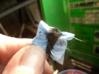
When changing the wire I also change out the "wire cleaning pad" :thumbsup:

See how much sh!t it wipes off of the wire? :eek:
SAM_9955.JPG
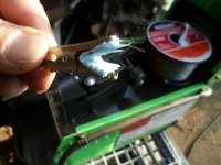
New "cleaning pad" ready for installation (it's just a folded-up piece of shop rag/paper towel stuff in an Alligator clip):cheers2:
SAM_9956.JPG
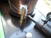
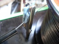
Cleaning pad installed on the wire :p
SAM_9957.JPG
As you can see, the wire just runs thru the cleaning pad, before entering the welder
...& most any contaminates get wiped off & collected in the pad :sifone:
SAM_9960.JPG
 

Functional Artist

Well-known member
Messages
5,654
Reaction score
3,293
Location
Toledo, Ohio
When building structural stuff, there is the strength of the material (itself)
...& there is strength in/of the design (itself)
The best designs try to incorporate both concepts, as much as possible. :bannana:

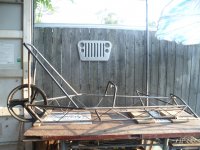
I designed the main frame to be made from strong but, kinda heavy water pipe (~1 lb. per ft)
...& the main cross members too
...but, for most of the braces, I'ma gonna try & use some smaller/lighter material (1/4" rod) :thumbsup:

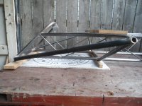
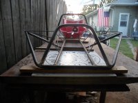
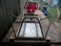
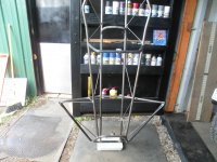
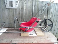
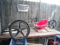
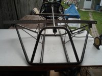
Front axle supports

Profile
SAM_9980.JPG
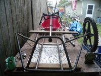
Frontal view
SAM_9975.JPG
Another frontal view
SAM_9974.JPG
* I didn't do any kinda math
...but, this 1/4" rod is pretty strong
...& probably ~75% less material, than the 1/2" Schedule 40 water pipe that the rest of the frame is made outta.\
...so, they are less bulk & hopefully less weight too ;)

Testing will tell us for sure :p

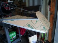
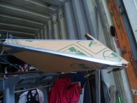
** It's kinda difficult ta see the aerodynamics, that I've incorporated into the front
...but, they are there :2guns:
 

Functional Artist

Well-known member
Messages
5,654
Reaction score
3,293
Location
Toledo, Ohio
Figurin' the gear ratio for a 20" bicycle wheel

I measured how far a 20 bicycle wheel travels, by marking the tire & workbench
SAM_9994.JPG
...& then rolling it until the mark (on the tire) went all of the way around, until it got to the bottom again
SAM_9995.JPG
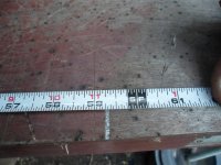
According to this, a 20" bicycle tire travels about 59 1/4"
...but for easier math let's say 60" ;)
SAM_9998.JPG
Theoretical specs
MY-1020 48V 1,000W motor has a max RPM (under load) of ~3,000's
It'll have a 10 tooth drive sprocket (for #35 chain) on the motor
...& maybe a 60 tooth driven sprocket, on the rear wheel

So, using the:

Ballpark Equation
MS/GR=ASxTC=IM/FT=FMxHR=FHxMM= MPH

Motor Speed/Gear Ratio=Axle Speed x Tire Circumference = Inches per Minute traveled/Foot(12) = Feet per Minute traveled x Hour(60) = Feet per Hour traveled x MPH Multiplier(.000189) = Miles Per Hour


If the motor does 3,000 RPM's
...& were running (for this example) 6:1 gear ratio
...& the bicycle tires have a ~60" cir.

Then, the math would look like:
3,000/6 = 500 (axle speed)
500 x 60 = 30,000 (inches per min traveled)
30,000/12 = 2,500 (feet per min traveled)
2,500 x 60 = 150,000 (feet per hour traveled)
150,000 x .000189 = 28.35 MPH

Hmmm, 23MPH isn't super fast
...but, a good starting point :thumbsup:

A 60 tooth #35 chain sprocket is ~7.3"
...& so, a ~7.3" sprocket, on a ~20 wheel, is still a less than 50% sprocket to wheel ratio :huh:

IIRC on most go karts, the sprocket to wheel ratio is more like 75% (like a 7" - 8" sprocket on a ~12" wheel) :unsure:
SAM_0001 (1).JPG
 

Functional Artist

Well-known member
Messages
5,654
Reaction score
3,293
Location
Toledo, Ohio
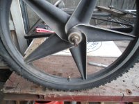
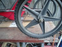
I ordered these BMX 6 spoke wheels (1 rear wheel with freewheel & 2 front wheels)
https://www.ebay.com/itm/195397518210
...(2) of these rotors
https://www.ebay.com/itm/175716099348?var=475102205451
...(2) of these calipers (180mm)
https://www.ebay.com/itm/275959525534

Once everything gets here, I gotta try-n-figure out how ta get them to "play nice" together :thumbsup:

Like figuring how to get the rotors securely attached to the front rims :unsure:
...& fabricating a couple of caliper mounts, for the front spindles that I haven't made yet :huh:

According to the rule book,

9 BRAKES and AXLES
1. At least two wheels must have brakes.
2. Brakes must be fitted to two wheels of the same axle. Either both front wheels or both rear wheels depending on vehicle construction.
3. The two brakes must have separate actuation cables. If both brakes are to be actuated by a single hand or foot lever then both cables should be attached to the lever.
4. Regenerative braking is permitted in addition to conventional brakes.
5. The vehicle must not roll if pushed while brakes are applied. The vehicle must also be able to demonstrate a straight stop from a speed of 25 MPH in less than 40 feet.
6. Axles supported at both ends must have a diameter of at least 3/8"(10mm).
7. Axles supported only on one end must have a diameter at least ½"(12mm)
8. Safety wire or cotter pins must be used to secure cantilevered wheel axle nuts. Nylon lock nuts and double nuts alone are not acceptable

Also, gotta figure out how to mount a 60T (or maybe a 72T) sprocket to the freewheel, on the rear wheel :popcorn:
 

Functional Artist

Well-known member
Messages
5,654
Reaction score
3,293
Location
Toledo, Ohio
Thinkin' about designin' & makin' a couple of spindles ta mount the front wheels :idea2:

We have (2) options:
Spindles, like on go karts
...or forks, like on bicycles

IMO dual forks would be a bit more complicated
...& look kinda dorky on a kart (just my opinion)
...so, I'm goin' with spindles :)
Didin' some research, according to the rulebook: :popcorn:

9 BRAKES and AXLES

6. Axles supported at both ends must have a diameter of at least 3/8"(10mm)
7. Axles supported only on one end must have a diameter at least ½"(12mm)


So, #9.6 says if using forks (axle supported on both ends) the minimum axle size permitted is ~3/8"
...& #9.7 says, if using spindles (axle only supported on one end) the minimum axle size is ~1/2"

* Now we have a new question, how to install a 1/2" axle (& bearings) in a bicycle wheel :unsure:


Also, I'm gonna incorporate some King Pin Inclination to this one (probably ~8* - 10* of inclination) :thumbsup:
...so, the King Pin or "hinge" that the wheel pivots on, is angled toward the center of the "contact patch", of the tire

This should help relieve some of the lateral stress off of the axle/center of the front wheels, in turns
...by directing some of that force, downwards into the contact patch ;)
SAM_0010 (1).JPG
Maybe something like this :2guns:
SAM_0012 (1).JPG
A closer view :cheers2:
SAM_0013 (1).JPG
 

Functional Artist

Well-known member
Messages
5,654
Reaction score
3,293
Location
Toledo, Ohio
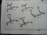
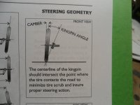
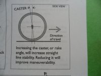
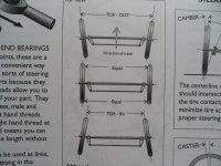
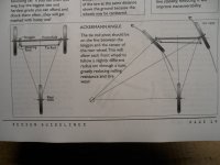
Almost forgot, the rule book has lots of info, about steering geometry

Page 18, shows some of the various steering concepts
SAM_9875.JPG
Page 19, explains & illustrates
Camber & King Pin Inclination
SAM_9876.JPG
Castor
SAM_9877.JPG
Toe in & Toe out
SAM_9878.JPG
Ackermann Angle
SAM_9879.JPG
 

Functional Artist

Well-known member
Messages
5,654
Reaction score
3,293
Location
Toledo, Ohio
Why did you name it Polaris?
...after the Slingshot?


Nope!

I wasa jammin' to some old Megadeth (Rust in Peace) while thinkin' about & designing this chassis
...& the perfect racing "talkin' trash" phrase "popped in my ear"

"Tremble you weaklings
...cower in fear

I am your ruler
...land
...sea
...& air"

For reference (& your entertainment) enjoy :cheers2:
 

Functional Artist

Well-known member
Messages
5,654
Reaction score
3,293
Location
Toledo, Ohio
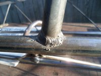
I tac welded the Boss Tubes on to the ends of the spindle supports (or nacelles)
...at ~10* Negative Camber
SAM_0059.JPG
...& ~10* Positive Castor
SAM_0057.JPG
After measuring, I put a straight edge, across from boss tube to boss tube, just to be sure that they were nice-n-aligned :thumbsup:

* Notice the nacelles are made up of (4) triangles
...on (4) different planes 🤓
SAM_0055.JPG
 

Functional Artist

Well-known member
Messages
5,654
Reaction score
3,293
Location
Toledo, Ohio
I received my bicycle wheels today :wai:
...& gotta see if I can upgrade the axle & bearings from a 3/8" axle up to a 1/2" axle

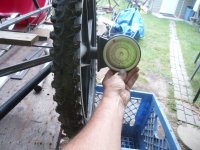
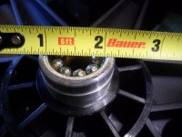
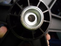
Here are the stock bearings (with axle removed)
SAM_0070.JPG
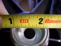
Measurement
SAM_0071.JPG
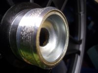
Looks like the bearing "race" maybe removable
SAM_0072.JPG
Another view
SAM_0073.JPG
Better measurement
SAM_0074.JPG
I think, if that "race" is removed, cartridge bearings can be installed & used ;)

What do you think, Hack? :unsure:
 

Functional Artist

Well-known member
Messages
5,654
Reaction score
3,293
Location
Toledo, Ohio
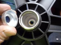
OK did it :wai:
Bearing race removed
SAM_0077.JPG
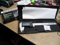
Got out my fancy digital caliper
...& of course, the battery is dead :mad2:
SAM_0078.JPG
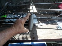
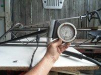
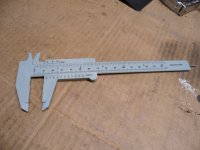
Plan B (this one ain't dead) :thumbsup:
SAM_0079.JPG
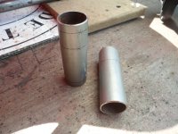
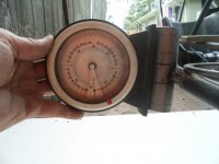
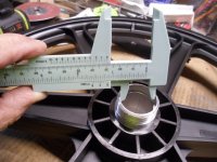
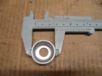
Measured the inside of the rim
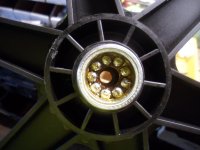
SAM_0080.JPG
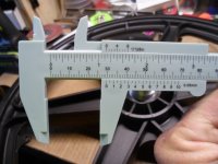
This pic seems a bit clearer ;)

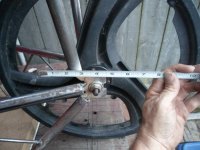
It looks like it's a little bit bigger than 1 1/8"
...or ~29mm
SAM_0081.JPG
I measured the outside of the bearing race too
...& it seems like it's closer to 30mm (maybe for a snug fit inside of a 29mm opening?)
SAM_0083.JPG
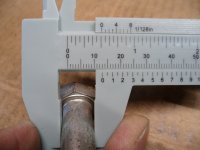
I measured a 1/2" bolt, that I'll be using for an axle, with the bearings
...& it looks ta be 1/2" &/or 13mm
SAM_0086.JPG
So, I'ma thinkin' I'ma needin' 30mm OD x 13mm ID bearings

Does this sound right?
...& do they make such a thing?
 

Master Hack

Well-known member
Messages
4,330
Reaction score
6,985
Location
Mountain top Labratory
Probably not. But there are options.
Little bigger than 1.125? sure would be nice to know EXACTLY how much. 1.130? .140?
There are metric bearings and there are inch. Maybe we hit a metric number, maybe we hit an inch number?
Are you stuck on a 1/2 bolt?

get a battery for the digital calipers
 
Top