You are using an out of date browser. It may not display this or other websites correctly.
You should upgrade or use an alternative browser.
You should upgrade or use an alternative browser.
New build in progress
- Thread starter WillMatrix
- Start date
Bansil
Painter of gnomes....
 ugh....
It's tomorrow................ today


WillMatrix
Member
- Messages
- 251
- Reaction score
- 22
Took it out for a spin
Attachments
-
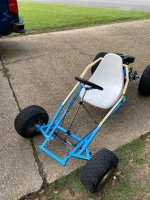 C68F0F1C-25EA-4806-A563-6FAB5A24E824.jpeg3.7 MB · Views: 15
 -
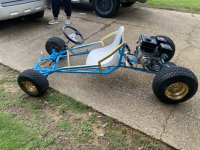 791BD4BA-1D91-4D83-BF51-9E5B9579FC64.jpeg6.8 MB · Views: 17
 -
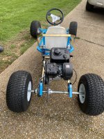 4E043978-2224-4D2B-AE2A-217ABC7EC7E9.jpeg3.4 MB · Views: 15
Functional Artist
Well-known member
Um...that's it!?Took it out for a spin

How about some commentary?
...tell us about your ride

We wanna know more
..."spill the tea"
* Oh yea, thanks for the pics

...looks good!

Bansil
Painter of gnomes....
X2 
How did suspension work?
brah...you can't leave us hanging, any video
I have my 1st public ride planned out already....I'm going for ice-cream like our resident electro scientist did going for a shake, but I will be on dirt and asphalt and not get pulled over
(Fingers crossed)
Wife wants to know how rear suspension worked, she has bad back and worried about bouncing
WillMatrix
Member
- Messages
- 251
- Reaction score
- 22
To be honest I need stiffer springs because it bottoms out. But once I get stiffer suspension it should work out excellent because the suspension does smooth out the ride. I’m going to figure out how to upload a video
Functional Artist
Well-known member
He, He that was an interesting dayX2
I have my 1st public ride planned out already....I'm going for ice-cream like our resident electro scientist did going for a shake, but I will be on dirt and asphalt and not get pulled over
(Fingers crossed)
I think the police officer, just wanted to check out the kart
Here is the video
...if anyone is interested
WillMatrix
Member
- Messages
- 251
- Reaction score
- 22
I need help! How do I get more turn radius out of this cart? I’m turning perfect I just want to be able to pull a 180 with much less finesse and effort
Functional Artist
Well-known member
Do you have Ackerman on your kart?I need help! How do I get more turn radius out of this cart? I’m turning perfect I just want to be able to pull a 180 with much less finesse and effort
If you don't know what Ackerman is
...you probably don't have it
I discuss/describe it while building my Excalibur kart
(see post #38)
(1) 2020 - Excalibur Electric Racing kart | Page 2 | DIY Go Karts
WillMatrix
Member
- Messages
- 251
- Reaction score
- 22
Ackerman? I don’t know the guy but I will take a close look at your videoDo you have Ackerman on your kart?
If you don't know what Ackerman is
...you probably don't have it
I discuss/describe it while building my Excalibur kart
(see post #38)
(1) 2020 - Excalibur Electric Racing kart | Page 2 | DIY Go Karts
madprofessor
"Loose Cannon Creations"
Wow! Straight axle turns are inherently difficult already, as one rear wheel pushes and the other drags. Without any ackermann angle in the steering you're probably pushing the front tires as much as steering them.
Remember this ackermann nugget: String tied to exact center of rear axle should pull tight in a straight line across the kingpin bolt of the spindle you're setting up (right or left). The spindle's arm should also be in an exact straight line with the string.
That's it.
Remember this ackermann nugget: String tied to exact center of rear axle should pull tight in a straight line across the kingpin bolt of the spindle you're setting up (right or left). The spindle's arm should also be in an exact straight line with the string.
That's it.
Bansil
Painter of gnomes....
That's why throttle is your friend just inner tire...we DD'd welded and lunchbox locked rears for years....15 years ago wifey took out a bunch of girlfriends to dinner in her Rodeo....locked rear and front...the ...CHirp....chirp...in parking lots makes folks turn and look
just inner tire...we DD'd welded and lunchbox locked rears for years....15 years ago wifey took out a bunch of girlfriends to dinner in her Rodeo....locked rear and front...the ...CHirp....chirp...in parking lots makes folks turn and look WillMatrix
Member
- Messages
- 251
- Reaction score
- 22
I don’t understand anything past string in the exact middle of the axel. Please give me a more clear understandingWow! Straight axle turns are inherently difficult already, as one rear wheel pushes and the other drags. Without any ackermann angle in the steering you're probably pushing the front tires as much as steering them.
Remember this ackermann nugget: String tied to exact center of rear axle should pull tight in a straight line across the kingpin bolt of the spindle you're setting up (right or left). The spindle's arm should also be in an exact straight line with the string.
That's it.
Functional Artist
Well-known member
Ackermann
"Ackermann steering geometry is a geometric arrangement of linkages in the steering of a car or other vehicle designed to solve the problem of wheels on the inside and outside of a turn needing to trace out circles of different radii.
It was invented by the German carriage builder Georg Lankensperger in Munich in 1817, then patented by his agent in England, Rudolph Ackermann (1764–1834) in 1818 for horse-drawn carriages.
The intention of Ackermann geometry is to avoid the need for tyres to slip sideways when following the path around a curve.
A simple approximation to perfect Ackermann steering geometry may be generated by moving the steering pivot points inward so as to lie on a line drawn between the steering kingpins and the centre of the rear axle. The steering pivot points are joined by a rigid bar called the tie rod which can also be part of the steering mechanism, in the form of a rack and pinion for instance. With perfect Ackermann, at any angle of steering, the centre point of all of the circles traced by all wheels will lie at a common point. Note that this may be difficult to arrange in practice with simple linkages, and designers are advised to draw or analyse their steering systems over the full range of steering angles.
Modern cars do not use pure Ackermann steering, partly because it ignores important dynamic and compliant effects, but the principle is sound for low-speed maneuvers. Some racing cars use reverse Ackermann geometry to compensate for the large difference in slip angle between the inner and outer front tyres while cornering at high speed. The use of such geometry helps reduce tyre temperatures during high-speed cornering but compromises performance in low-speed maneuvers."
https://en.wikipedia.org/wiki/Ackermann_steering_geometry
I employ this concept on my Excalibur kart
...& kinda go into a bit of detail as to how & why
...& I even show how I extended the spindle "arms" to compensate
I know it's kinda long
...but, ya should read thru the entire thread
Ya may find it kinda interesting
* I really had the "glexis" (technical term from Flyin' Hillbilly ) "dialed in" (another technical term)
...& the kart handled/maneuvered superb
** Listen for the "bing"
"Ackermann steering geometry is a geometric arrangement of linkages in the steering of a car or other vehicle designed to solve the problem of wheels on the inside and outside of a turn needing to trace out circles of different radii.
It was invented by the German carriage builder Georg Lankensperger in Munich in 1817, then patented by his agent in England, Rudolph Ackermann (1764–1834) in 1818 for horse-drawn carriages.
The intention of Ackermann geometry is to avoid the need for tyres to slip sideways when following the path around a curve.
A simple approximation to perfect Ackermann steering geometry may be generated by moving the steering pivot points inward so as to lie on a line drawn between the steering kingpins and the centre of the rear axle. The steering pivot points are joined by a rigid bar called the tie rod which can also be part of the steering mechanism, in the form of a rack and pinion for instance. With perfect Ackermann, at any angle of steering, the centre point of all of the circles traced by all wheels will lie at a common point. Note that this may be difficult to arrange in practice with simple linkages, and designers are advised to draw or analyse their steering systems over the full range of steering angles.
Modern cars do not use pure Ackermann steering, partly because it ignores important dynamic and compliant effects, but the principle is sound for low-speed maneuvers. Some racing cars use reverse Ackermann geometry to compensate for the large difference in slip angle between the inner and outer front tyres while cornering at high speed. The use of such geometry helps reduce tyre temperatures during high-speed cornering but compromises performance in low-speed maneuvers."
https://en.wikipedia.org/wiki/Ackermann_steering_geometry
I employ this concept on my Excalibur kart
...& kinda go into a bit of detail as to how & why
...& I even show how I extended the spindle "arms" to compensate
I know it's kinda long
...but, ya should read thru the entire thread
Ya may find it kinda interesting
* I really had the "glexis" (technical term from Flyin' Hillbilly
) "dialed in" (another technical term) ...& the kart handled/maneuvered superb
** Listen for the "bing"
madprofessor
"Loose Cannon Creations"
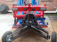
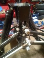
The link below is for the spindles on my current kart. Look at the picture of them, the bolt sticking up vertically out of it is the "kingpin" bolt, what the spindle swings (steers) back and forth on. The "C"-shaped bracket it goes through is the "spindle bracket" that's welded solid to the A-arms of a suspension system, or just welded solid to the kart on a rigid. I'll try to find a pic showing mine to attach. The bolt sticking out horizontally is the axle, mine is 3/4", while most use 5/8". The flat bar sticking out 90 degrees from the axle is the "spindle arm", and the hole in the end of it is where your tierod bolts to it.
Those spindles have "zero" ackermann angle, because the axle and arm are 90 degrees apart. When you point your front tires straight forward the axle would be pointing 90 degrees to the side. Those spindles would have the arms pointing straight backwards for a "trailing arm" setup, or pointing straight forward for a "leading arm" setup like mine. (I'll make next kart a "trailing arm" setup.)
Correct ackermann angle would have those arms pointing in a straight line toward the exact center of the rear axle, whether "trailing" like my next kart, or "leading" like my current one. Now you can see what the string stretched tight and passing over the center of the kingpin bolt is for. Imagine the arm isn't welded yet, and you can just swing it around a little bit so it falls perfectly in line with your string, (instead of pointing straight forward or backward) that's where you weld it. That's why folks order spindles that are not welded yet, so they can position the arm in the right spot. When it's correct the string would pass over not only the kingpin bolt, but also over the tierod bolt holding the tierod to the arm.
I didn't change the direction of my spindle arms. I welded on some tabs that changed the position of my tierod connection, so a string from my rear axle center would indeed pass over both my kingpin and my tierod bolts. After all, it's not really the angle of the arm that counts, its the location of the bolthole at the end of the arm for your tierod that has to be in line.
That's how you get your inside tire in a turn to turn more sharply than the outside tire, which must carve a wider circle.
Complete Spindle Set - 4-1/2" x 3/4" | 421434 | BMI Karts And Parts
(First pic below is an old experimental setup where I used an offset angle of some spacers to get tierod bolts in line, since they had to be raised up anyway. You can clearly see that with the steering going to the right in that pic that the inside tire is turned more sharply than the outside tire. That's correct ackermann angle. All of that's now gone, next pic is part of current setup that lowered my tierods with a chaindrive. Offset tabs now get tierod bolts in line.)
Attachments
-
 100_0168.JPG2.6 MB · Views: 7
 -
 IMG_20210710_163030 (1).jpg2.8 MB · Views: 7
Last edited:
WillMatrix
Member
- Messages
- 251
- Reaction score
- 22
I got a better understanding of what you are saying but still understand that I’m a person with noooooo prior knowledge of this stuff. Do you have an example to show this Ackerman guy with you actively applying it?The link below is for the spindles on my current kart. Look at the picture of them, the bolt sticking up vertically out of it is the "kingpin" bolt, what the spindle swings (steers) back and forth on. The "C"-shaped bracket it goes through is the "spindle bracket" that's welded solid to the A-arms of a suspension system, or just welded solid to the kart on a rigid. I'll try to find a pic showing mine to attach. The bolt sticking out horizontally is the axle, mine is 3/4", while most use 5/8". The flat bar sticking out 90 degrees from the axle is the "spindle arm", and the hole in the end of it is where your tierod bolts to it.
Those spindles have "zero" ackermann angle, because the axle and arm are 90 degrees apart. When you point your front tires straight forward the axle would be pointing 90 degrees to the side. Those spindles would have the arms pointing straight backwards for a "trailing arm" setup, or pointing straight forward for a "leading arm" setup like mine. (I'll make next kart a "trailing arm" setup.)
Correct ackermann angle would have those arms pointing in a straight line toward the exact center of the rear axle, whether "trailing" like my next kart, or "leading" like my current one. Now you can see what the string stretched tight and passing over the center of the kingpin bolt is for. Imagine the arm isn't welded yet, and you can just swing it around a little bit so it falls perfectly in line with your string, (instead of pointing straight forward or backward) that's where you weld it. That's why folks order spindles that are not welded yet, so they can position the arm in the right spot. When it's correct the string would pass over not only the kingpin bolt, but also over the tierod bolt holding the tierod to the arm.
I didn't change the direction of my spindle arms. I welded on some tabs that changed the position of my tierod connection, so a string from my rear axle center would indeed pass over both my kingpin and my tierod bolts. After all, it's not really the angle of the arm that counts, its the location of the bolthole at the end of the arm for your tierod that has to be in line.
That's how you get your inside tire in a turn to turn more sharply than the outside tire, which must carve a wider circle.
Complete Spindle Set - 4-1/2" x 3/4" | 421434 | BMI Karts And Parts
(First pic below is an old experimental setup where I used an offset angle of some spacers to get tierod bolts in line, since they had to be raised up anyway. You can clearly see that with the steering going to the right in that pic that the inside tire is turned more sharply than the outside tire. That's correct ackermann angle. All of that's now gone, next pic is part of current setup that lowered my tierods with a chaindrive. Offset tabs now get tierod bolts in line.)
madprofessor
"Loose Cannon Creations"
Watch the video link below from about 3 minutes into it through 12 minutes. He's just a good ole boy doing a rough setup of steering for ackermann angle, but you get to see one of the plainest displays of physically building it I've seen. He's building a short kart, so the ackermann is really a pronounced angle, very easy to see and understand, and you could even do yours exactly the same.
Note: His kart is a "trailing arm" setup, where the spindle arms extend from the spindles back toward the rear, "trailing" behind the axles. A "leading arm" setup like mine would just have those spindle arms extending from the spindles forward toward the front, "leading" the axles.
If he had built a leading arm setup on that short kart with his very pronounced angle of the spindle arms, the ends of the arms would probably have butted into his tires, so that wouldn't have worked.
My 8' wheelbase is so long that my ackermann angle is really not a very sharp angle, so I have room to do the leading arm setup.
Racing Mower Build Pt.4 (How To Do Steering Ackerman) - YouTube
WillMatrix
Member
- Messages
- 251
- Reaction score
- 22
Wow!!! Now I get it but my spindles came welded. Is there anything I can do so I can get some adjustability?Watch the video link below from about 3 minutes into it through 12 minutes. He's just a good ole boy doing a rough setup of steering for ackermann angle, but you get to see one of the plainest displays of physically building it I've seen. He's building a short kart, so the ackermann is really a pronounced angle, very easy to see and understand, and you could even do yours exactly the same.
Note: His kart is a "trailing arm" setup, where the spindle arms extend from the spindles back toward the rear, "trailing" behind the axles. A "leading arm" setup like mine would just have those spindle arms extending from the spindles forward toward the front, "leading" the axles.
If he had built a leading arm setup on that short kart with his very pronounced angle of the spindle arms, the ends of the arms would probably have butted into his tires, so that wouldn't have worked.
My 8' wheelbase is so long that my ackermann angle is really not a very sharp angle, so I have room to do the leading arm setup.
Racing Mower Build Pt.4 (How To Do Steering Ackerman) - YouTube
madprofessor
"Loose Cannon Creations"
You can cut them off and reweld them at an ackermann angle, but like I said I didn't do that. Laying a little piece of flat bar over the tierod connection hole on the spindle arm, you can have the flat bar extend where the string says the tierod hole should be, and weld the flat bar to the spindle arm. Drill your tierod hole in the flat bar at that spot where the string says the hole should be. It's basically what I did.
Functional Artist
Well-known member
Yup, ya gotta make a bracketYou can cut them off and reweld them at an ackermann angle, but like I said I didn't do that. Laying a little piece of flat bar over the tierod connection hole on the spindle arm, you can have the flat bar extend where the string says the tierod hole should be, and weld the flat bar to the spindle arm. Drill your tierod hole in the flat bar at that spot where the string says the hole should be. It's basically what I did.
...& add it to your spindle
...like this
https://www.diygokarts.com/community/attachments/sam_4081-jpg.118933/