OzFab
Well-known member
And Jim is also correct about how you can adjust both the effective length of the spacer as well the overall positioning of the whole works by using washers of various thicknesses...... (You know, some in front, some behind, to get the sprocket where you need it.....)
Hold up, the way I understood it, Jim was saying don't use washers, at all, which I agree with...
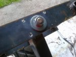
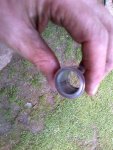
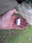
Ideally, you want the spacer to be a bit longer than required (around 1mm), that way, the retaining washer on the end doesnt bottom out on the shaft before it has a good contact on the sprocket.
Also, on the other end, near the casing, you may need to grind a small chamfer on the outside to make sure it clears the case...
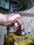
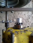
 5 lb capacity fish scale graduated in ounces just so I could measure the rotational drag on a spindle to establish the correct preload on the angular contact bearings I just replaced.


 Pat
Pat
