Simon Thomas
New member
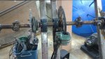
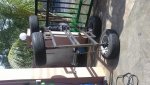
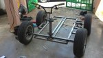
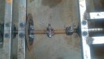
I re-positioned the bearing units from top of frame to underneath the frame.
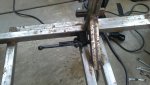
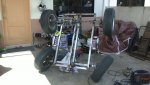
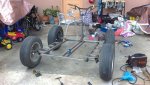
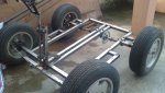
Not a great view to see as you can see lots my working stuffs are scatterred all over the place. Infact this is the real looks when works were in progress.
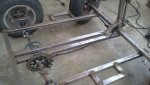
Not a great view to see
as you can see lots my working stuffs are scatterred all over the place. Infact this is the real looks when works were in progress.Attachments
-
 10122011660.jpg107.9 KB · Views: 35
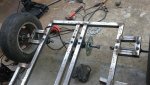

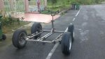
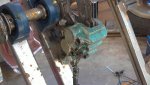
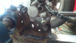
 . Last weekend, I managed to put the brake system.