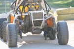
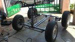
There was really nothing wrong with your first design other than using threaded rod and running the cart onto high of traction surfaces and the added stress/leverage from the larger diameter tires your using.
Even our ATV's will strip out the hardened hub and axle splines if we run them on high traction surfaces to much and dont do it correctly.
To do it correctly we have to lean enough on the outside of the turn to lift the inside tire while turning so it can slip otherwise it just wants to push straight and it stress's the driveline.
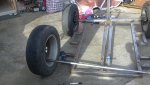
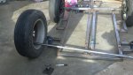
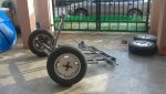
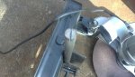
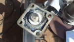
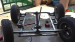
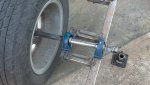
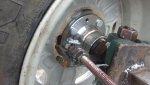
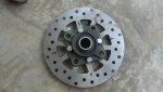
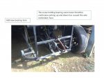
What I cant see for certain in the picture is if this design has a differential or not but anyway I was thinking of a much simpler and doable design with the supplies I have seen you working with.
Did your first cart ever buck or feel like it was binding up when turning corners, tight corners especially and tend to want to push thru a turn rather than turn tight and easy on high traction surfaces.
(I would think it had to, I have felt it many times on my atv)
From your postings I assume you know how/why a differential works but if you are uncertain there are some great illustrations on the net.
I've seen guys shatter a 1"-1/4 or so drive axle on concrete trucks just from locking the diff and backing out onto pavement and turning.The stuff in those drivelines is pretty tough to be moving 80'000 lbs but can only handle so much stress and will pop if used wrong.
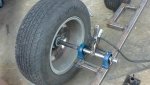
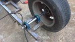
I'm still stuck on you having to much traction and no differential action as the problem.
 03122011609.jpg78.5 KB · Views: 15
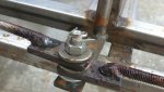 03122011608.jpg72.7 KB · Views: 14
 03122011610.jpg70.2 KB · Views: 17


 .
.