You are using an out of date browser. It may not display this or other websites correctly.
You should upgrade or use an alternative browser.
You should upgrade or use an alternative browser.
Model T fiberglass body go kart project
- Thread starter Stew
- Start date

JTSpeedDemon
2019 Build Off Winner!
Just as long as the axle bearings are straight! Might wanna take a straightedge to it.
The Professor
New member
The majority of your frame and brake mounting bracketry look identical to my BRAT kart. It's too bad you're modifying the kart as much as you are, I was hoping to crib off your choice in brake parts as that and the chain are the last pieces in my mini-restoration of the kart.
I don't know if the drum/sprocket on mine are original or not to where restoring mine would be of any help. Also if you were to see this frame up close you would see it was not worth preserving, there were so many holes drilled and repair welds all over this thing. I don't know if the original brake drum and sprocket are supposed to be welded together like on mine, but these sure aren't coming apart again, this is one of several reasons I decided to go the route I did.


The brake on mine looked like a standard brake band setup and chain is #35 type
If you haven't already, Google "FW & Associates Mini Cars" and you'll find several restores out there, here is a good one I ran across.
http://bricklin-sv-1-build-history.com/photo_16.html
The brake on mine looked like a standard brake band setup and chain is #35 type
If you haven't already, Google "FW & Associates Mini Cars" and you'll find several restores out there, here is a good one I ran across.
http://bricklin-sv-1-build-history.com/photo_16.html
Last edited:
I got the cross pieces mocked up for the motor mount.
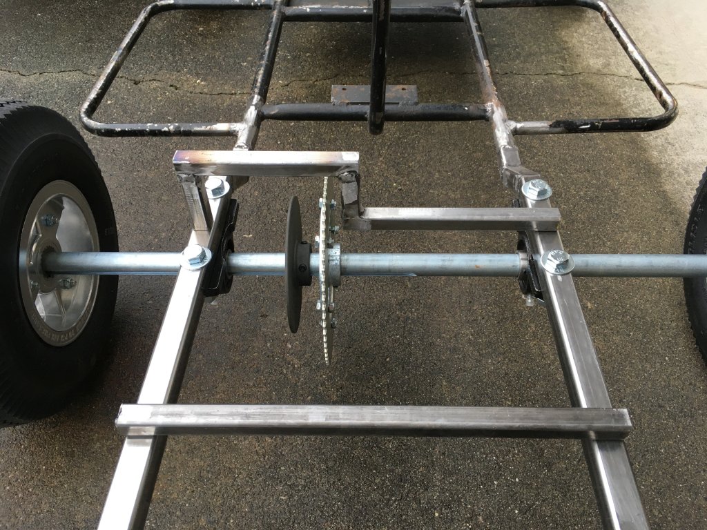

When test positioning the motor my clever idea of going up and over the sprocket was going to get in the way of the chain no matter where I positioned the motor plate. I tried laying that front cross member down so it would go around the back side of the sprocket but it still interfered.
While staring at it I came up with an even better way to mount that motor plate where I want it and keep the sprocket and brake disc between the frame rails, I almost got the new design finished but ran out of daylight. I'm starting my work week so it might be a few days before I make more progress.
Last edited:
You are moving along quite nicely
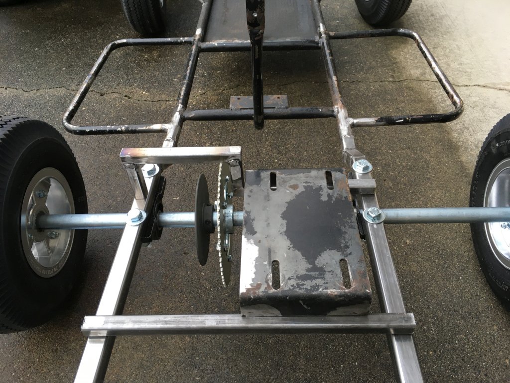
The engine mounting bracket is done.

I'm having a hard time with my welding being consistent, one time I'll do a decent weld like below and the next time it'll be total crappola.


This is the engine plate in position ready to be welded:
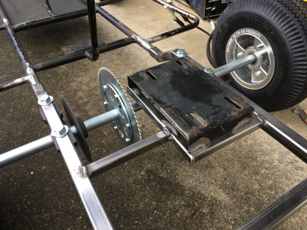

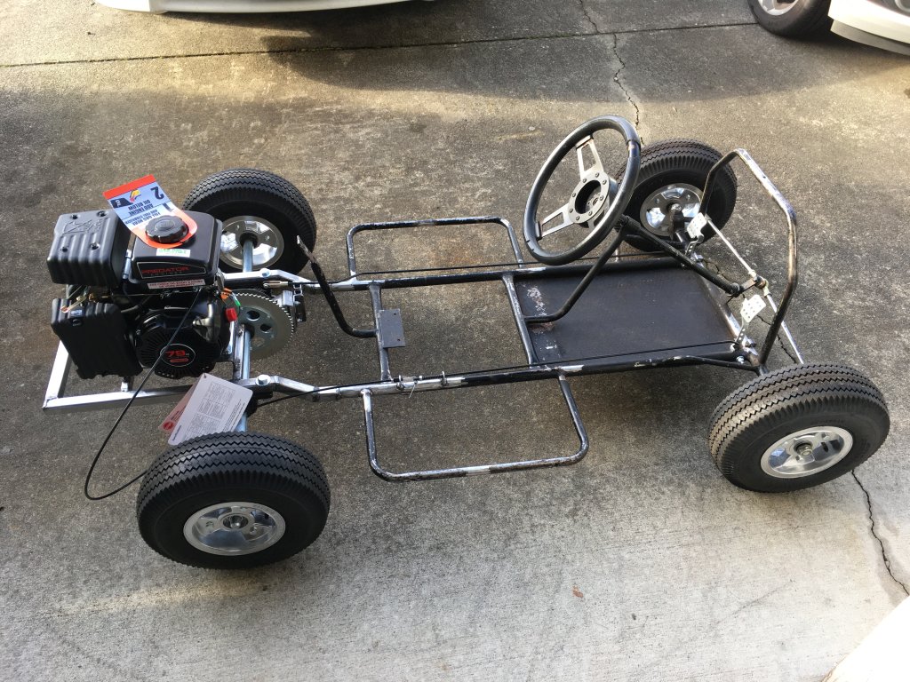
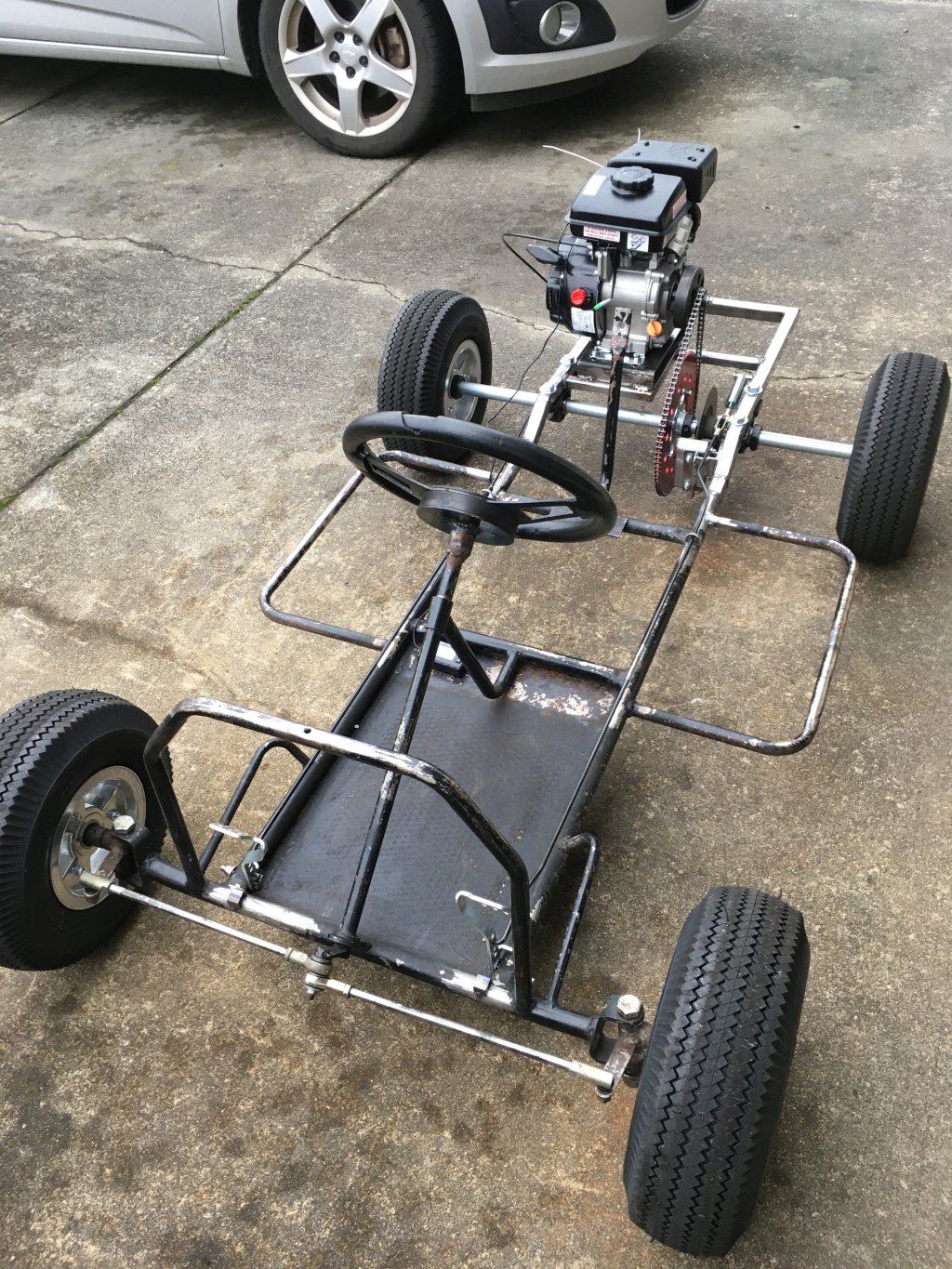
And here is the engine sitting in position, it's a new Predator 79cc 3 HP, it is really light and doesn't make much power so that bracket should hold just fine.
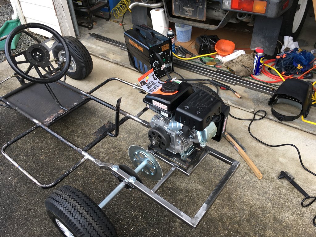

I also almost have the caliper bracket done and I've ordered the chain. It is getting close to being able to do a shake down run, I can't wait!
I'm having a hard time with my welding being consistent, one time I'll do a decent weld like below and the next time it'll be total crappola.
This is the engine plate in position ready to be welded:
And here is the engine sitting in position, it's a new Predator 79cc 3 HP, it is really light and doesn't make much power so that bracket should hold just fine.
I also almost have the caliper bracket done and I've ordered the chain. It is getting close to being able to do a shake down run, I can't wait!
Last edited:
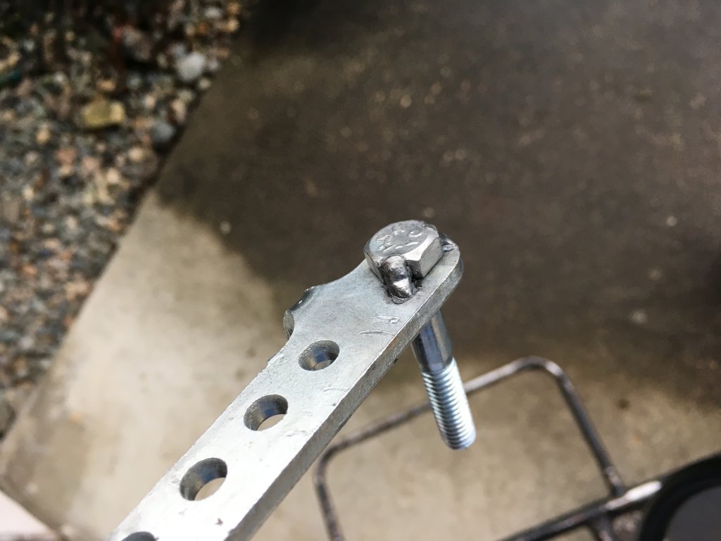
I tapped out the awful studs from these cheap pedals in favor of slightly better hardware from Lowe's, I may tack the new bolts on I haven't decided yet.


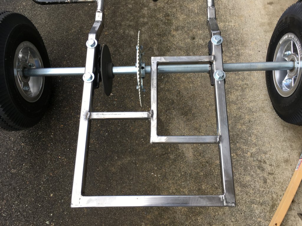
Here's the caliper bracket I came up with:


Welded to the frame:
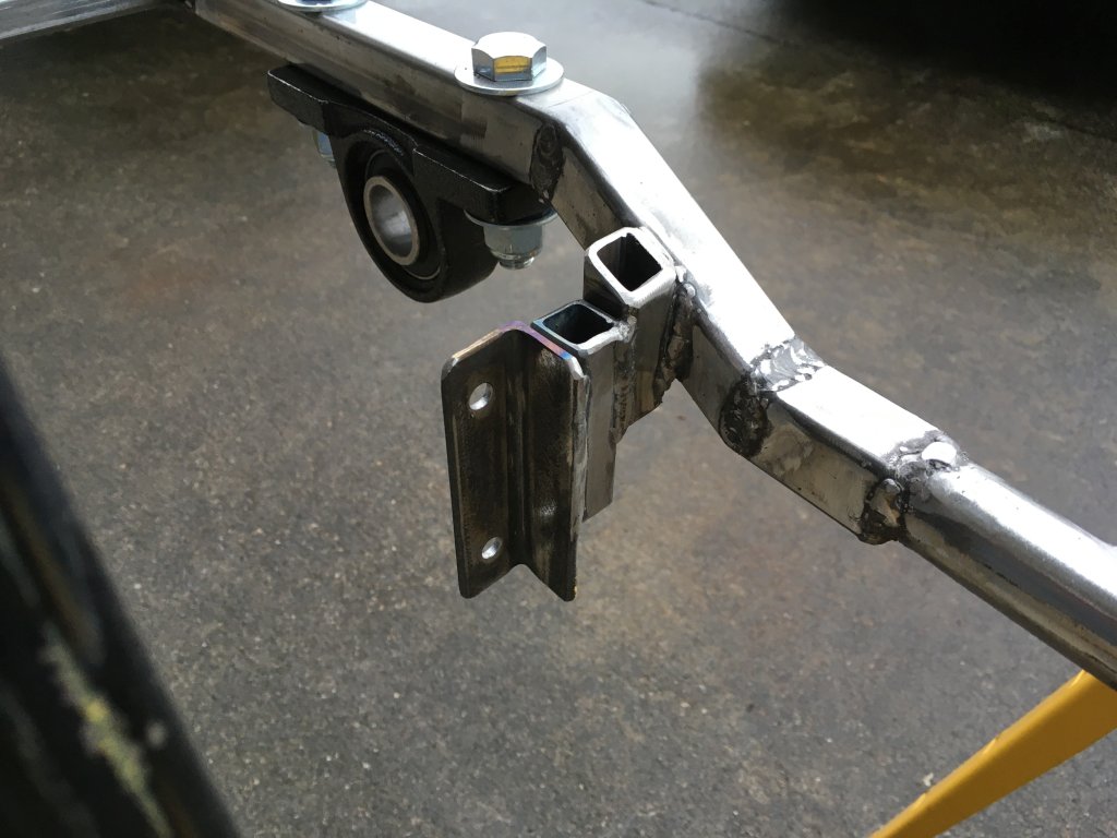

And mocked up, not tightened down:


Here's the caliper bracket I came up with:
Welded to the frame:
And mocked up, not tightened down:
Last edited:
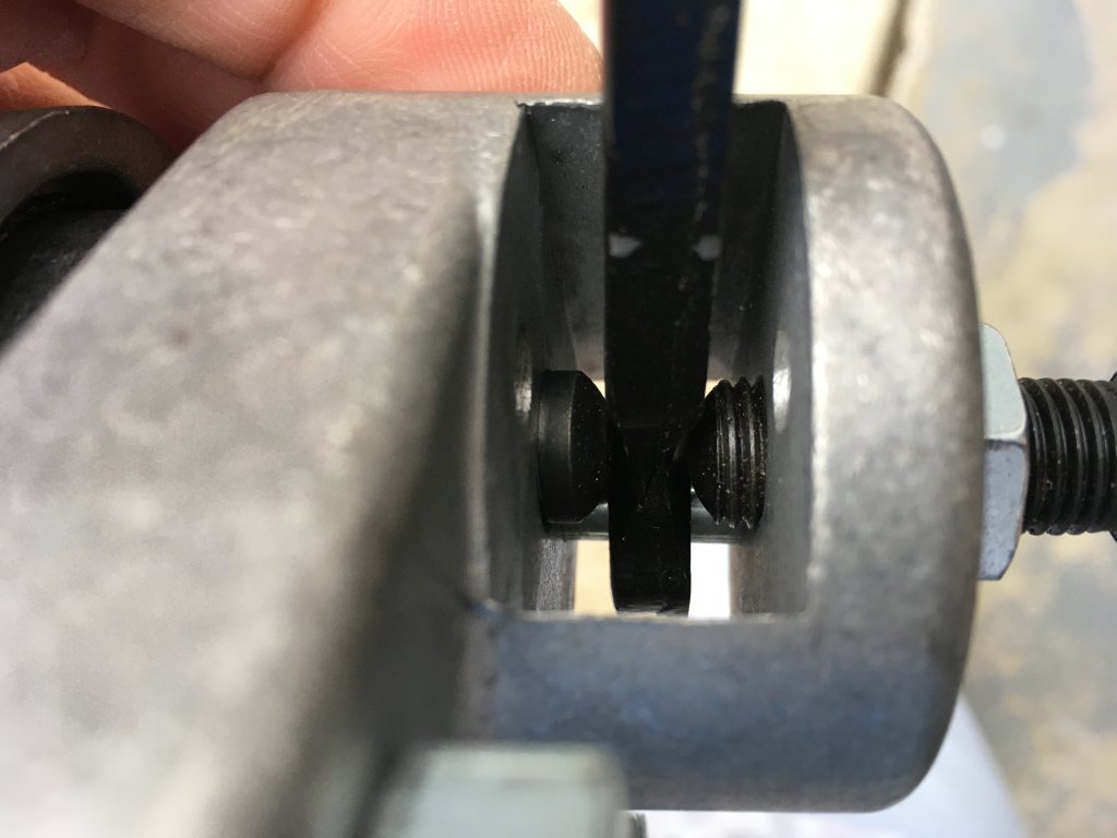
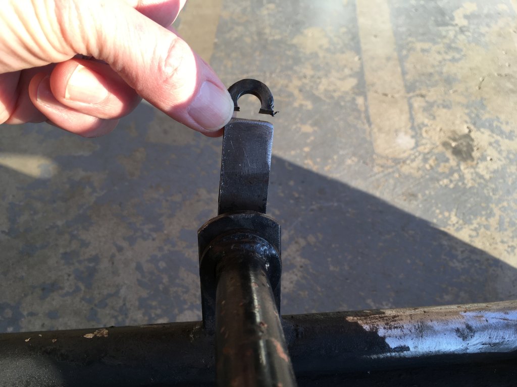
Got a little more work done today. With the new wider wheels there isn't as much thread left on the spindles and I couldn't find thin 3/4"-10 nylon lock nuts, so I whipped out the hack saw and made my own.


Not pictured but also done was cutting a couple links off the new chain and fitting that, the brake rod was fitted too so it can stop. The last thing before taking it for a test spin is hooking up the throttle. I think I've got it figured out how to hook it up to the engine but I'll have to wait until the bicycle cable adjusters I ordered from Amazon get here before I know for sure.
These are what's holding me up, grrr
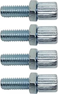
Last edited:
MrBracket
AKA: Moto-Mule ;)
Fun Project! I really like that body!!! (the one on the kart, that looks like an old Ford, from Krogers... Don't want anyone getting any strange ideas.... LOL )
Can't wait to see this little paddy wagon RIP!!
Can't wait to see this little paddy wagon RIP!!
MrBracket, yep I am having fun, can't think of a better way to learn some welding skills!
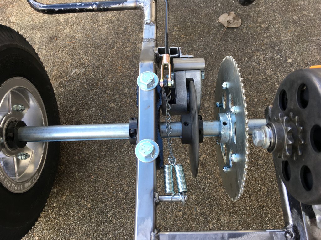
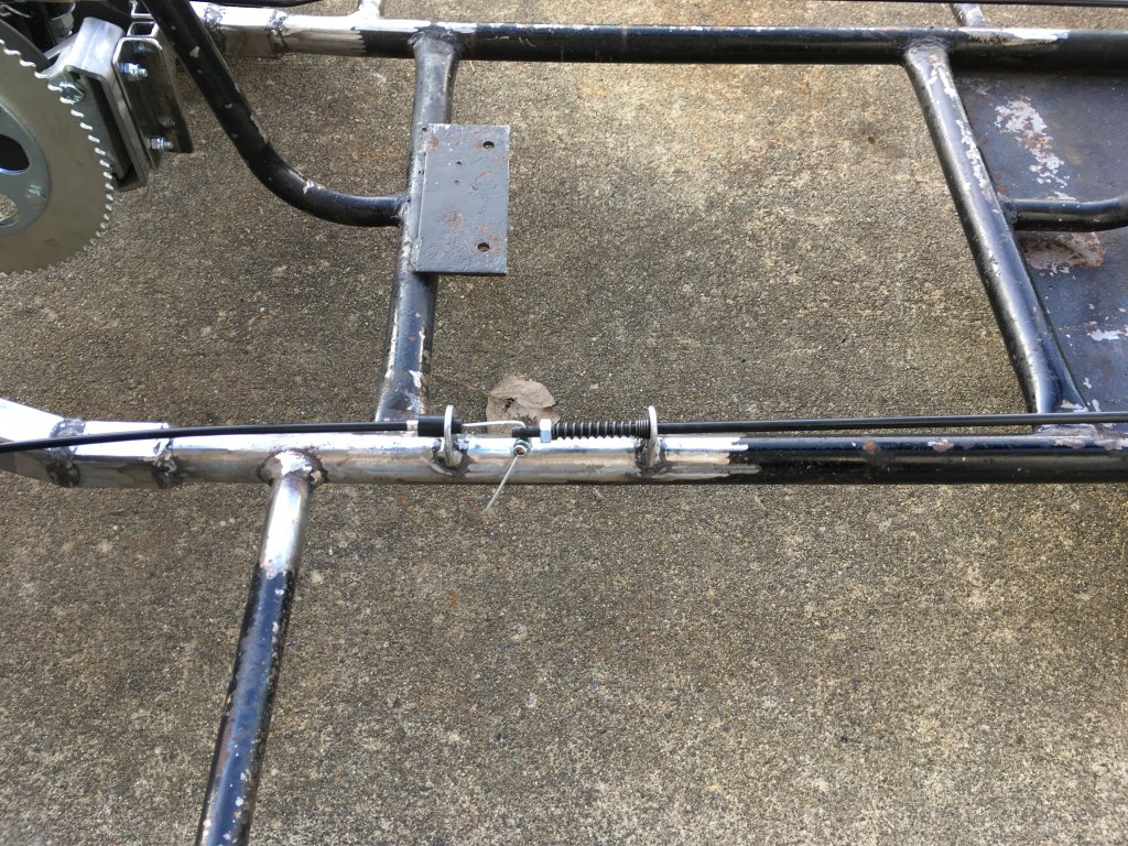
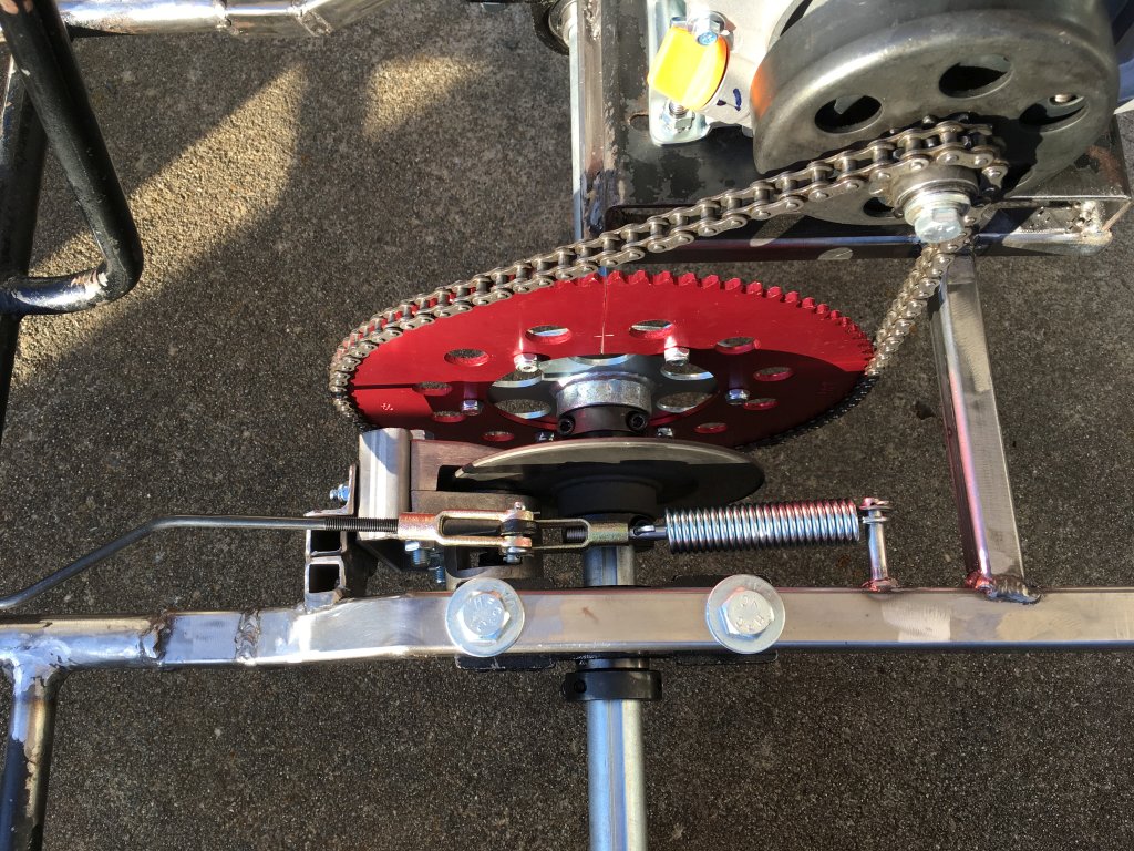
Got a little more done and am ready to take it around the block, I live in a small neighborhood in a rural area with almost zero traffic and it's normal to see guys around here zipping around on dirt bikes and things, so my neighbors won't mind.
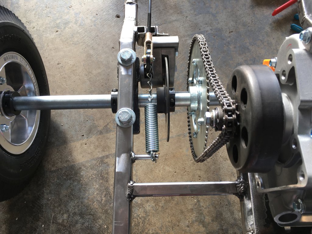
I welded on a pin for the brake return spring:
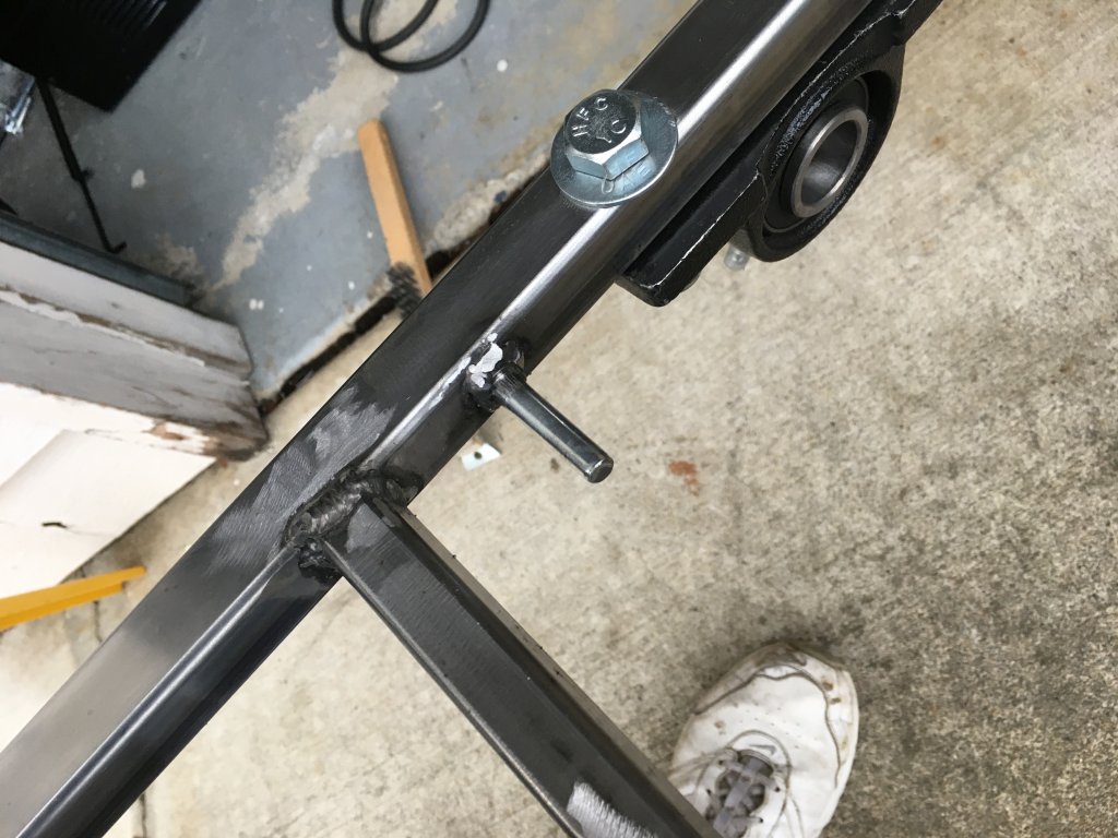

And here it is all hooked up. The chain will be replaced with a rod and clevis like on the brake rod. These manual disc calipers stick on when you apply the brake hard, I doubled up the return spring but will go with a single stronger one later.

I tacked the bolts to the pedals which makes them less floppy when mounted, and welded on pedal stops out of a bit of 3/4" square tube.


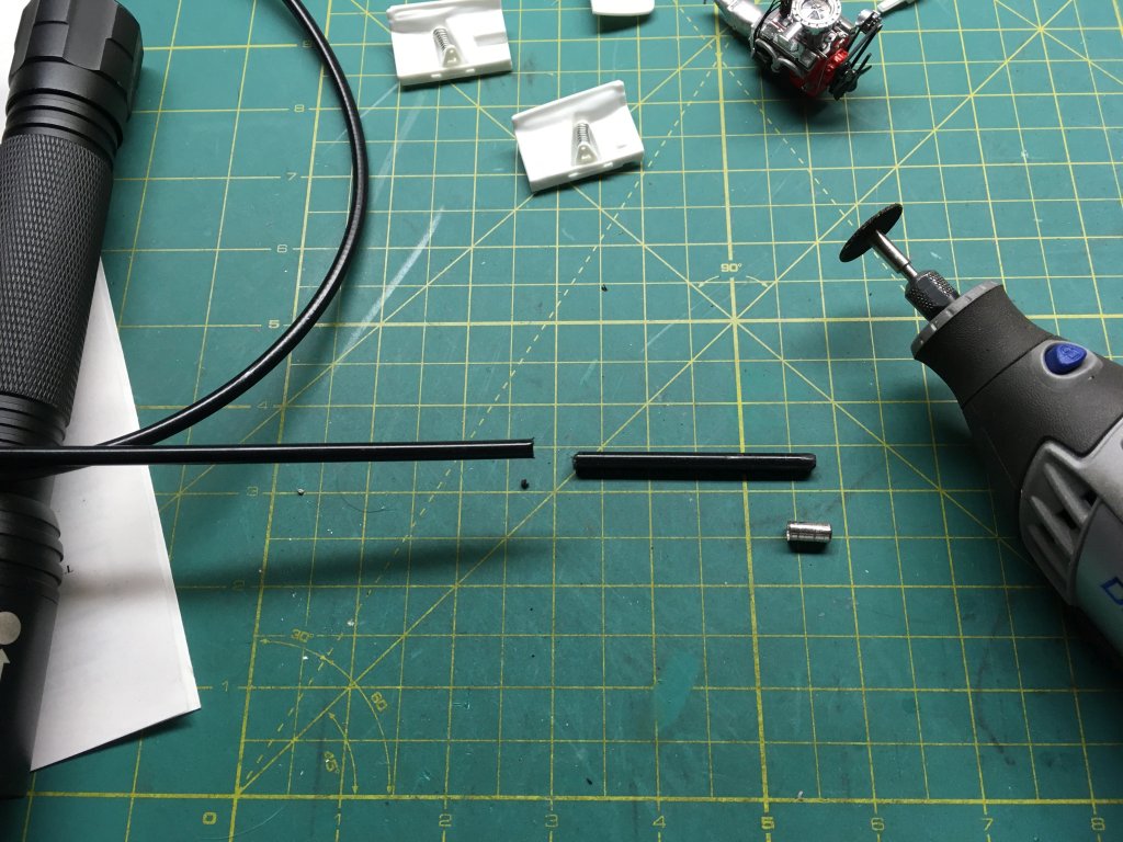
In case you couldn't tell, most of the parts I've been ordering are from AZUSA, they are reasonably priced and for the most part they have been working well on this frame. The throttle cable sheath was a bit too long so I slid the chrome end piece off and cut off about 2.5" with the Dremel, fits good now.

With the throttle cable fixed I needed a way to mount it. Every FW & Associates frame I've seen had tabs for the throttle but I couldn't see any evidence of them ever existing on mine.
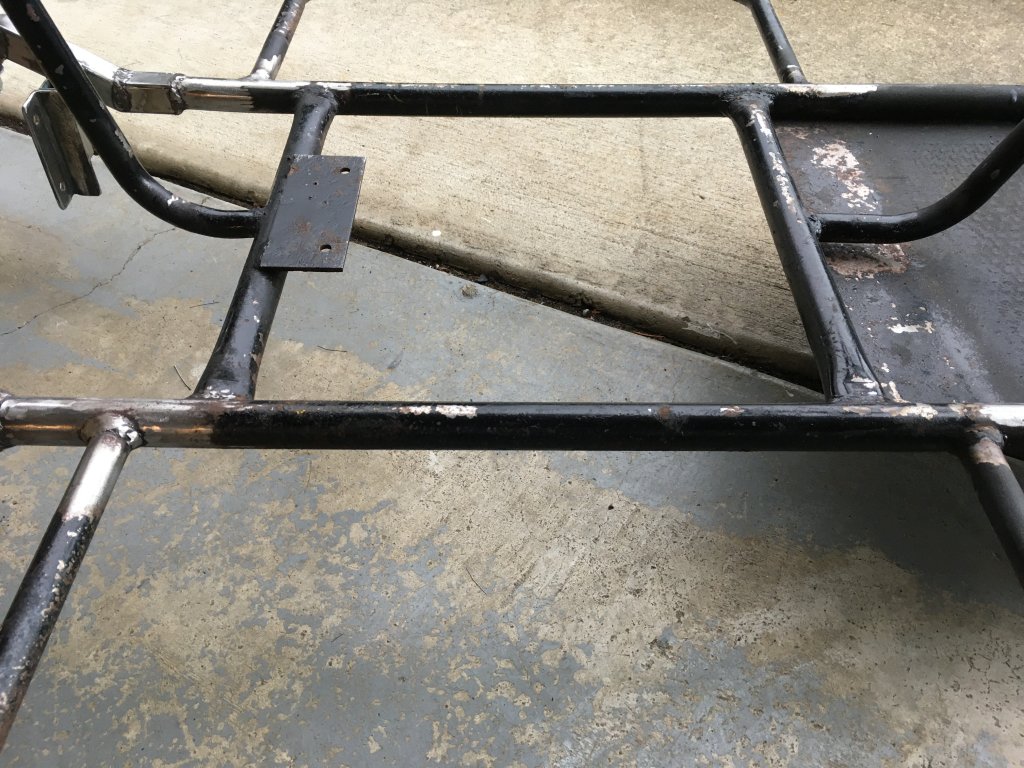

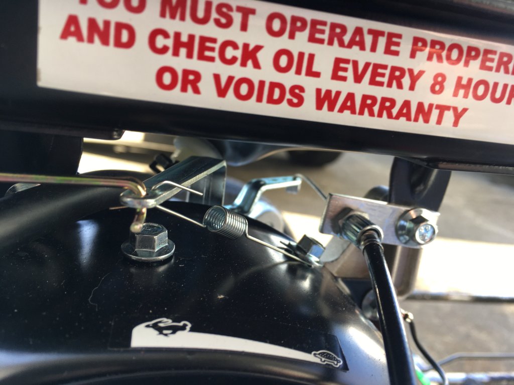
Got tabs welded on and throttle cable installed. This setup is exactly like the AZUSA go karts.

There is no nice built-in way to connect a throttle cable to the Predator 79cc like there is on the 212cc. I removed the throttle lever and used a small piece of aluminum to connect it like this. Nothing modified and is adjustable.

Just have to put some gas and oil in it, zip tie the throttle cable out of the way, wrap the tach/hour meter around the plug wire and she's ready for a test ride!


Got a little more done and am ready to take it around the block, I live in a small neighborhood in a rural area with almost zero traffic and it's normal to see guys around here zipping around on dirt bikes and things, so my neighbors won't mind.
I welded on a pin for the brake return spring:
And here it is all hooked up. The chain will be replaced with a rod and clevis like on the brake rod. These manual disc calipers stick on when you apply the brake hard, I doubled up the return spring but will go with a single stronger one later.
I tacked the bolts to the pedals which makes them less floppy when mounted, and welded on pedal stops out of a bit of 3/4" square tube.
In case you couldn't tell, most of the parts I've been ordering are from AZUSA, they are reasonably priced and for the most part they have been working well on this frame. The throttle cable sheath was a bit too long so I slid the chrome end piece off and cut off about 2.5" with the Dremel, fits good now.
With the throttle cable fixed I needed a way to mount it. Every FW & Associates frame I've seen had tabs for the throttle but I couldn't see any evidence of them ever existing on mine.
Got tabs welded on and throttle cable installed. This setup is exactly like the AZUSA go karts.
There is no nice built-in way to connect a throttle cable to the Predator 79cc like there is on the 212cc. I removed the throttle lever and used a small piece of aluminum to connect it like this. Nothing modified and is adjustable.
Just have to put some gas and oil in it, zip tie the throttle cable out of the way, wrap the tach/hour meter around the plug wire and she's ready for a test ride!
Last edited:
Haha first, second and third test drives are done! 
It's not real powerful, obviously, with that 79cc motor on there but it does eventually get up to speed. With the 11T clutch, 72T sprocket and 14" diameter tires it was getting up to 23 mph on my speed app pretty easily. According to a spreadsheet I whipped up to calculate rpms and speeds that should be right around 3600 rpm, the way I hooked up the throttle I bypassed the governor so I didn't want to go much faster than that on a motor with all of 10 minutes of run time on it. Plus it was about 5 or 6 degrees above freezing and it gets real cold at 23 mph!
Now that I'm confident that everything is working as planned, considering this IS my first time fabricating anything like this, I can move forward with more upgrades and repairs. None of my welds broke apart so I was happy about that lol.
I did upgrade the brake return spring, this one is 16 lb and works much better than the two smaller 6 lb springs although I'm still not real happy with the sticky feeling mechanical caliper.
Last edited:
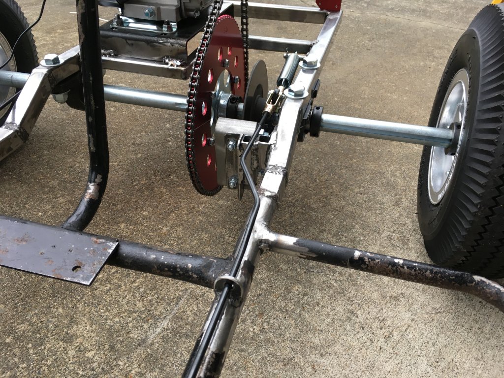
Got a couple parts in, waiting for a couple more...
To try and improve the sticky feeling of the caliper I took a Q-tip dipped in my wheel bearing grease container and dabbed a little on either side of the lever where it spreads apart the two metal studs. This actually helped a lot and since I won't be driving it in dusty conditions it should be fine.


I also got an 85T sprocket to replace the 72T, the picture make the 85T sprocket look huge but it's not as big as the picture makes it look. And according to my spreadsheet my top speed will only go down a little, from 22.9 mph to 19.4 mph.


This go kart is more about lower speed driving, I'm okay losing a couple mph off the top to gain a little more low-end power, think parade type driving. The red-shaded cells calculate their values from what's entered in the white cells.

To try and improve the sticky feeling of the caliper I took a Q-tip dipped in my wheel bearing grease container and dabbed a little on either side of the lever where it spreads apart the two metal studs. This actually helped a lot and since I won't be driving it in dusty conditions it should be fine.
I also got an 85T sprocket to replace the 72T, the picture make the 85T sprocket look huge but it's not as big as the picture makes it look. And according to my spreadsheet my top speed will only go down a little, from 22.9 mph to 19.4 mph.
This go kart is more about lower speed driving, I'm okay losing a couple mph off the top to gain a little more low-end power, think parade type driving. The red-shaded cells calculate their values from what's entered in the white cells.
Last edited:
Looking good! How much clearance will you have with the new 85T sprocket?
")
gegcorp2012
Active member
Hi @stew ,
Nice to hear you got in some test runs on the chassis... in winter time as well .
Welds are looking good too. Your metal prep is good so that always helps.
I like to use an auto darkening face shield because I can see what I am doing before I hit the trigger to weld. That makes it less frustrating flipping the hood and trying to start the bead in the right place.
Keep up the good work !
Sent from my SM-J700T using Tapatalk
gegcorp2012 - Thank you, I did end up getting an auto darkening helmet as well, the handheld one that comes with this welder is ridiculous, it might work ok but you definitely need both hands most of the time!
I had to get a new chain to fit the larger sprocket, once I got that on I took it for a few more test spins and I am really happy with this gearing. I got it up as high as 4300 rpms according to my hour/tach meter which is plenty high enough... I wonder how high these 79cc's will rev before you have to start worrying about things. It is completely stock and the governor hardware has not been removed. I've got 36 minutes on the engine it looks like. The 1P1R setting is the correct setting on these type of tachometers for this engine? With that setting it shows an idle speed just under 2000 rpms, I guess if it fires every revolution the spark on the exhaust stroke is a waste spark?


I got the brake return spring in it's final configuration, the lever on the caliper has two holes so I got another clevis and hooked it up to the second hole. It seems to work good and the brake feel is pretty spot on. I also welded on a guide bracket for the brake rod, it was flexing at the bends I made in the rod and this reduced that a lot.


Next things to tackle are figuring out a seat and re-doing the rear body mount. I think those are the last things before I can take everything back off to strip the frame and re-paint it.
I had to get a new chain to fit the larger sprocket, once I got that on I took it for a few more test spins and I am really happy with this gearing. I got it up as high as 4300 rpms according to my hour/tach meter which is plenty high enough... I wonder how high these 79cc's will rev before you have to start worrying about things. It is completely stock and the governor hardware has not been removed. I've got 36 minutes on the engine it looks like. The 1P1R setting is the correct setting on these type of tachometers for this engine? With that setting it shows an idle speed just under 2000 rpms, I guess if it fires every revolution the spark on the exhaust stroke is a waste spark?
I got the brake return spring in it's final configuration, the lever on the caliper has two holes so I got another clevis and hooked it up to the second hole. It seems to work good and the brake feel is pretty spot on. I also welded on a guide bracket for the brake rod, it was flexing at the bends I made in the rod and this reduced that a lot.
Next things to tackle are figuring out a seat and re-doing the rear body mount. I think those are the last things before I can take everything back off to strip the frame and re-paint it.
Last edited:
The other day I got the rear body mount welded on, I also want to brace it diagonally down to the frame but I'll still deciding on how to do that.

Today I got the steering sorted out. The tie rods, which I understand are lawn tractor throttle rods but seem to work really good as tie rods, had the threads cut to different lengths for some reason and the threads in the heim joints had been cross threaded or something and were in really bad shape. Further, the steering shaft arm bolt was too small for the diameter of the heim joints so there was all kinds of slop in the steering.


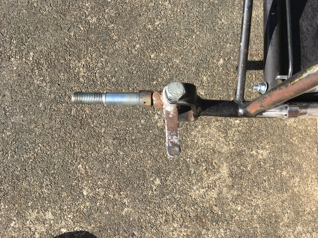
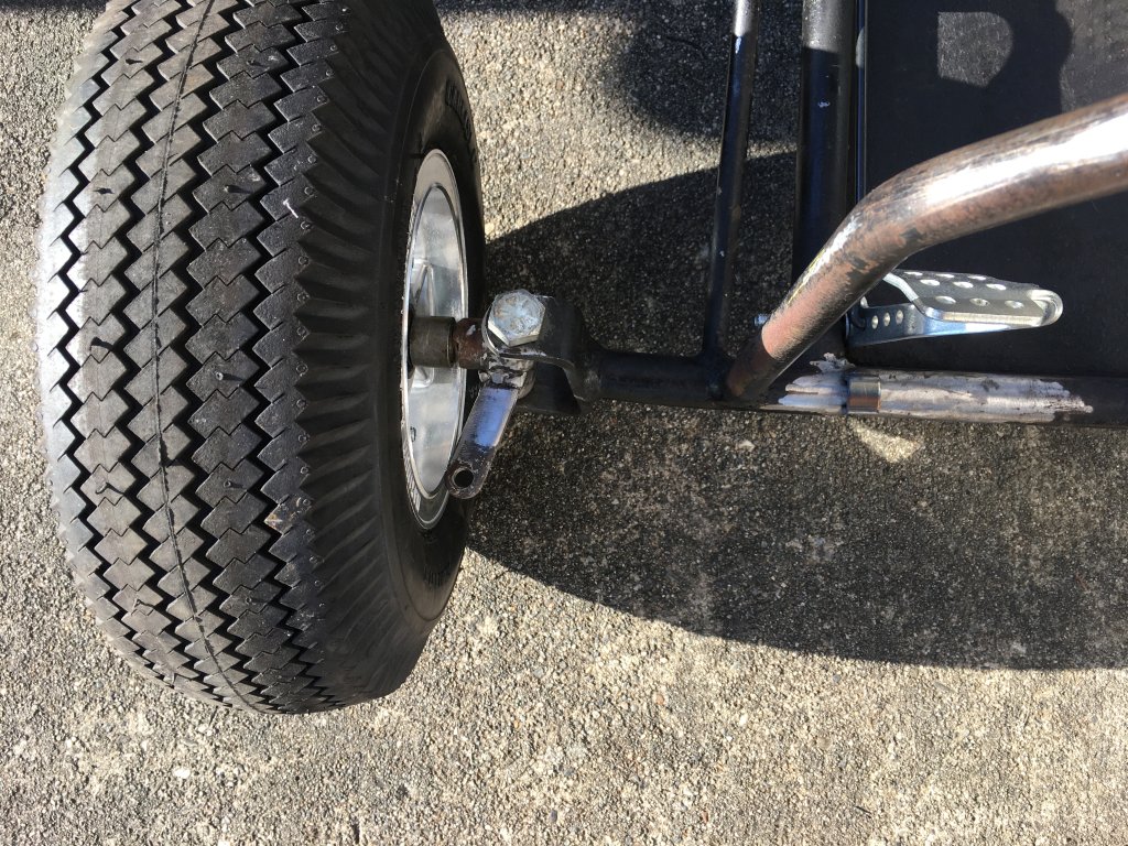
On top of all this the steering arm on the spindles were going the wrong way for ackerman angle, giving the result of anti-ackerman(?). When you would turn the outside tire was turning SHARPER than the inside rather than less. So I cut the steering arms off and welded them back on correctly for front pointing steering arms.
Wrong ackerman:

Correct ackerman:

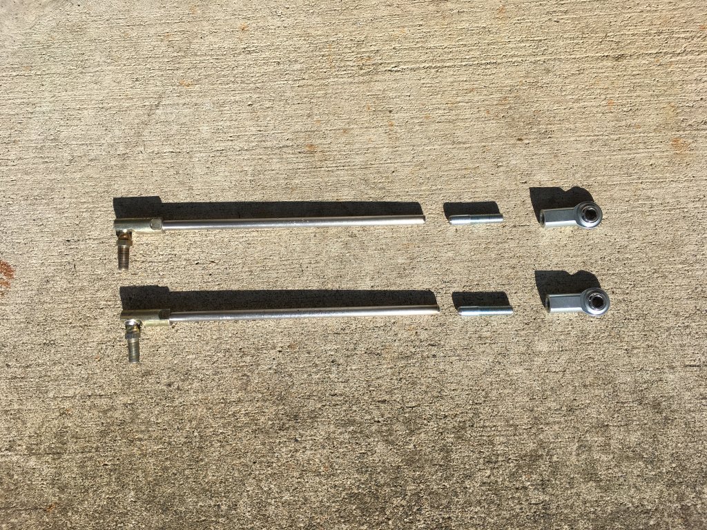
Here are the tie rods with the old thread cut off, ready to weld on new thread sections for the new heim joints:

And tie rods ready to be put back into service.

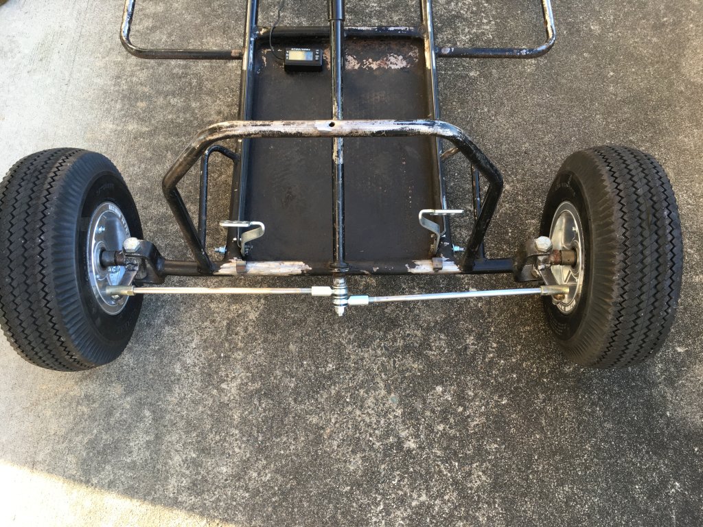
And finally the front end with corrected ackerman steering, re-done tie rods, new heim joints and new correct size steering arm shaft bolt. It steers much better now.

Next installment, figuring out a new seat!
Today I got the steering sorted out. The tie rods, which I understand are lawn tractor throttle rods but seem to work really good as tie rods, had the threads cut to different lengths for some reason and the threads in the heim joints had been cross threaded or something and were in really bad shape. Further, the steering shaft arm bolt was too small for the diameter of the heim joints so there was all kinds of slop in the steering.
On top of all this the steering arm on the spindles were going the wrong way for ackerman angle, giving the result of anti-ackerman(?). When you would turn the outside tire was turning SHARPER than the inside rather than less. So I cut the steering arms off and welded them back on correctly for front pointing steering arms.
Wrong ackerman:
Correct ackerman:
Here are the tie rods with the old thread cut off, ready to weld on new thread sections for the new heim joints:
And tie rods ready to be put back into service.
And finally the front end with corrected ackerman steering, re-done tie rods, new heim joints and new correct size steering arm shaft bolt. It steers much better now.
Next installment, figuring out a new seat!
Last edited:
After re-doing the spindle steering arms the steering was a little too quick, I cut off a bit from the steering shaft arm to slow it down a little. This did help some.

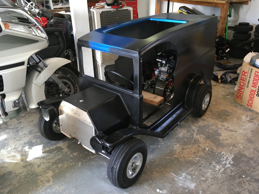
I finally was to the point where I needed to test fit the body, I had to tweak the side and front body mounts into position just a bit with the crowbar but got it sitting on there pretty good.

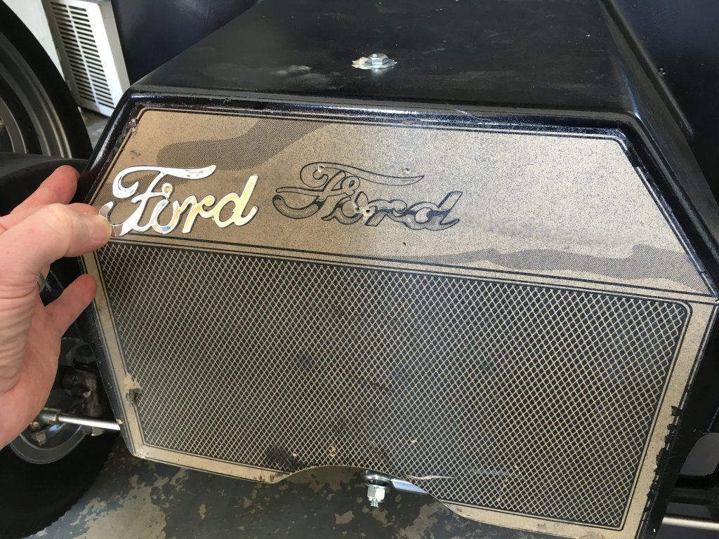
And a preview of some bits I got for the body... That front grill including the Ford script is one big sticker, I found a Ford script that will go nicely, still not sure how I'm going to recreate that grill effect with paint though.

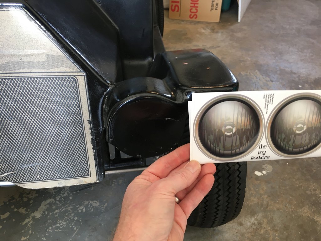
On Amazon I found some replacement stickers for a Power Wheels Jeep that will work perfect for the headlights:

I finally was to the point where I needed to test fit the body, I had to tweak the side and front body mounts into position just a bit with the crowbar but got it sitting on there pretty good.
And a preview of some bits I got for the body... That front grill including the Ford script is one big sticker, I found a Ford script that will go nicely, still not sure how I'm going to recreate that grill effect with paint though.
On Amazon I found some replacement stickers for a Power Wheels Jeep that will work perfect for the headlights:
Last edited: