Kart Klinic 32 Hot Rod

firemanjim

Just kartin' around....
Messages
5,247
Reaction score
87
Location
Houston Texas
Last night, I capped the ends of the swing arm. I also cleaned it up a little,and painted the corners where the fresh weld was starting to accumulate rust dust....
I haven't had the opportunity to make the spacers, we are fairly busy at work. I ended up cutting 2 spacers out of tubing, so I could assemble the rear end and start measuring for shocks, and mounts. My rear hubs come in today :)wai:) and I found 4 great used golf cart wheels and tires for $50, with hub caps..... I'll be picking those up Friday. The rear end is almost done. I need to get the sprocket and hub, and start fabricating the brake assemble.....
Last night, I also ordered a set of shocks from a Honda z50. I pulled one off my z50 to see what the spring rate felt like, individually. I think they might be perfect! If, when finished, they're are a little shy of ideal, I can always add a set, with no need to modify anything. Just add longer bolt, and put shocks on each side of the mount..... I was originally going to use some coil overs left over from my sandrail build, but thinking about it, unless I could come up with a way to make a mono shock fit, 2 of them are just going to be too stiff..... We will see what happens.
I'll post pics tonight, after I get my hubs.....
 

firemanjim

Just kartin' around....
Messages
5,247
Reaction score
87
Location
Houston Texas
ot a whole lot done. Been both busy,and lazy. After my 6 hour nap today,I decided I'd bend up some schedule 40 pipe to make my upper halo. First time to use the bender,so I was learning as I went. The rear half came out perfect. I was off y an inch on the front half.... Need better lighting.... LOL
Anyway,I'm going to go buy some more pipe tomorrow after work,then see how far I can get ,before I gotta quit using the chop saw. (I hate HOA's) I should have the main part of the cage done by Wednesday or Thursday.
The reason I'm using schedule 40 is because I have not had a chance to get to the steel supply . Their hours don't fit my work schedule. Its the ONLY reason this one is being built using pipe. Come income tax time,I'll be buying steel tube in bulk,couple hundred feet at a time. With a $400 order,you get free delivery,so might as well take advantage of it.....
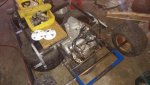
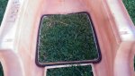
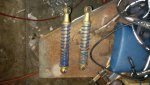
Here is a few pics. Those are the shocks I'm using for the rear. 110# spring rate with 3+" of travel. PERFECT!
The last pic shows how nice of a bend you can get,using the cheap harbor freight bender. No kinks at all,very very minute ovaling. I think its a great bender for the money. Just takes practice. I did not waste a single inch of pipe,from improper measuring,I'm getting the hang of it now....
 

Attachments

  • IMG_20141109_174515.jpg
    IMG_20141109_174515.jpg
    85 KB · Views: 18
  • IMG_20141109_174440.jpg
    IMG_20141109_174440.jpg
    79.4 KB · Views: 27
  • IMG_20141109_174308.jpg
    IMG_20141109_174308.jpg
    73.8 KB · Views: 16
  • 1415578352556.jpg
    1415578352556.jpg
    67.2 KB · Views: 15
  • IMG_20141109_174344.jpg
    IMG_20141109_174344.jpg
    74.1 KB · Views: 18

bo968

New member
Messages
3
Reaction score
0
HeyJim, Can you tell/show which front and rear hubs you are going with for the golf cart wheels? Are they the white ones you have in the above pic?

Thanks,
Bo
 

firemanjim

Just kartin' around....
Messages
5,247
Reaction score
87
Location
Houston Texas
Bo, the white hubs you see in that pic are for the rear. They are from BMI, and are described as "heavy duty". I believe they were $19.89 each.
The front hubs have been ordered and will be here mid week.... BUT for now, I can give you the part # I got and a link to the website...
http://www.surpluscenter.com/Wheels...l-Hubs/HIGH-SPEED-WHEEL-HUB-4-BOLT-1-1133.axd
I'm using the 1" stub axle as well, to build my own front spindles.:cheers2:
 

firemanjim

Just kartin' around....
Messages
5,247
Reaction score
87
Location
Houston Texas
:idea2:
Do you see anything wrong with this idea? The shock mounts I'm using are from BMI, part #010012, and it is 1&3/8" wide,1/8" thick. Gonna weld that on top of the swing arm. Then, using 1/8" plate, gonna make a mounting plate for the pillow block bearings. I am going to cut plate to encase the 1"x2" tube. Then add gussets to the bottom plate, to support the weight. (maybe leave enough on the outter side to add another pillow block bearing.)
I think the pic and description are clear enough for you to understand.
So, do you see anything wrong or potential problems with this? Speak up now, cause I want to start on this part very soon. The rear is almost done and I should have the front end parts this week too.
http://www.bmikarts.com/Shock-Mounting-Bracket_p_1289.html
That's a link to the mount.....
 

Attachments

  • __TEMP__dda63eab97f5b78cf864545ce8bb8ebd-1395142880_6958_IMG_20141109_221636.jpg
    __TEMP__dda63eab97f5b78cf864545ce8bb8ebd-1395142880_6958_IMG_20141109_221636.jpg
    50.2 KB · Views: 23

Half-breeder

"Edit" button removed
Messages
1,686
Reaction score
9
Can't see anything wrong w/ the plan. I think a 1/4" plate mount would do... so what you got planned seems overkill... but FORSURE solid!

I see no issues... unless a clearance issue arises , which only time will tell.
 

ML-TOYS

New member
Messages
2,908
Reaction score
19
Location
long island, new york
Looks great to me. The only thing i see is possibly what your concerned about. There is that chance of some flex and twist happening even with the small offset ods the shock and bearing. Working in a metal shop and a body shop i have seen some odd things happen that you think wouldnt.
If you are concerned with that i have another idea.
 

firemanjim

Just kartin' around....
Messages
5,247
Reaction score
87
Location
Houston Texas
Yeah, MLTOYS, kinda worried about twisting the tube, even though it's only like 13" long.... Kinda think I should add a pillow block bearing to the outside as well. What's your idea?
 

ML-TOYS

New member
Messages
2,908
Reaction score
19
Location
long island, new york
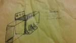
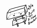
This may seem odd. I had to draw on my granddaughters drawing app. The bracket will be U shaped with thru holes bolted thru the swingarm. In the bottom of the bracket thru bolts for pillow block.
No welding and removable for pillow replacement and incase you need to relocate for some reason. If moved the existing holes in arm can then be plug welded shut.
The bottom thru bolts would be tight against the bottom of swing arm. This is just an option for keeping it alligned.
Its like taking that shock bracket and sliding it over the bottom.
 

Attachments

  • image.jpg
    image.jpg
    45.5 KB · Views: 2

itsid

Moderator
Staff member
Messages
11,563
Reaction score
246
Location
Ruhrpott [Germany]
So not inside as in "inside the tube", but inside as in "towards the center"...
I got that wrong when I read your PM ...

inside the tube would be cool though *shrugs* and absolutely no flexing whatsoever (straight line of force)...

Aaanyways, a single pillow block moved inwards isn't harming anything, especially not with gussets like that;
I do not even think that flexing is something to be really concerned about

But may I ask why you want to move it inwards and not just mount the pillow blocks under the swingarm?
(those two holes shouldn't be a problem right?)

'sid
 

firemanjim

Just kartin' around....
Messages
5,247
Reaction score
87
Location
Houston Texas
The reason I was going to put the bearings there,is so I could have elongated holes for more adjustment. After a some quick math, the shock mount is less than 3" long. The bolt holes for the pillow block is 4.135" ctc.....I'm going to use a solid chain, so there's no real reason to need more adjustment. Chain tensioner will take care of any slack. I guess I'm just going to drill holes in the swing arm for crush tubes, to mount the bearings. After thinking about it, with the 18" tires, I don't HAVE much room for adjustment, so going through the tube and only allowing for the 3/8" adjustment in the bearings base is the way to go.....
Thanks for the input, Gentlemen ...... :thumbsup:
 

2SlickNick

American Minibikes @ FB
Messages
2,758
Reaction score
30
Location
Mesa, AZ.
My fab skills and knowledge are probably just past novice at best.
I too don't foresee that twisting. The idea seems solid enough. My only question/suggestion would be in post #102 and pic#2 ..... Would be bracing or gussets for the motor cradle that comes off main frame.
Otherwise, I am loving this build.
 

OzFab

Well-known member
Messages
15,615
Reaction score
70
Location
Warwick Qld, Australia
This may seem odd. I had to draw on my granddaughters drawing app. The bracket will be U shaped with thru holes bolted thru the swingarm. In the bottom of the bracket thru bolts for pillow block.
No welding and removable for pillow replacement and incase you need to relocate for some reason. If moved the existing holes in arm can then be plug welded shut.
The bottom thru bolts would be tight against the bottom of swing arm. This is just an option for keeping it alligned.
Its like taking that shock bracket and sliding it over the bottom.

I like this idea, the only problem I forsee is, when you tighten the bolts to attach the bracket, the potential to crush the rail tube is very high...

So, now that the frame is welded & you can't access the tube, how do you get a sleeve inside? Watch this from about the 15 minute mark (so much easier than trying to explain it...)

As for the pillow block itself, If you use cup head bolts in a square hole & tack welded in place, you never need to remove the bracket...
 

firemanjim

Just kartin' around....
Messages
5,247
Reaction score
87
Location
Houston Texas
My fab skills and knowledge are probably just past novice at best.
I too don't foresee that twisting. The idea seems solid enough. My only question/suggestion would be in post #102 and pic#2 ..... Would be bracing or gussets for the motor cradle that comes off main frame.
Otherwise, I am loving this build.
Nick, I have braces cut to fit already, but won't put them in till final welding time. :thumbsup: good call....

I was going to suggest bolting thru but thought the shock bracket was going to be in the way.
:censored:
I didn't want to, but looks like its gotta be done.... I thought same as you, that's why I came up with that idea. Now I see that the bolts will be plenty spaced apart that there should be no clearance issues. I liked your idea though.In fact, so much, that, I will be using it when I build one of the two different summer time projects I'm planning....

I like this idea, the only problem I forsee is, when you tighten the bolts to attach the bracket, the potential to crush the rail tube is very high...

So, now that the frame is welded & you can't access the tube, how do you get a sleeve inside? Watch this from about the 15 minute mark (so much easier than trying to explain it...)

As for the pillow block itself, If you use cup head bolts in a square hole & tack welded in place, you never need to remove the bracket...
Well Tony, looks like I'm going to go through the frame with bolts. I already know how to put in crush tubes, learned the hard way... :oops:
That's a cool video series though, so I really appreciate that link for sure. :thumbsup::thumbsup:
Ok, take a potty break, as this might get long winded.... :popcorn:
Y'all back now? :thumbsup:
The bolt holes in the pillow block are .517", so I'm using 1/2" bolts to secure them. For the crush tube installation, I'm going to cut 4 pieces of 1/2" schedule 40, {which has an ID of .610" (or close to it, depending on manufacturer ) and an OD of .880"} to 2.5" long. I'm going to drill 7/8" holes through the frame tube for them. Then I'll center the crush tubes in them,so 1/4" sticks out on both sides. I will drill 1" holes, spaced out the same as the crush tubes, in a (2 really) piece of flat stock cut to 1.25x5.25x .125" thick. I will weld both the top and bottom of the crush tubes to the frame tube. I'll flip it over, then clamp the plate onto the frame tube, over the crush tubes. Finally, I'll grind down the crush tubes, so that they are flush or just past flush, with the plate. The pillow block will sit on the plate, like a big washer, with the bolts holding everything in place. :thumbsup:
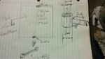
Next.... My front steering set up.... Look at the pic. It's self explanatory. Do you see anything wrong with this idea? 3/4" heims ends for top and bottom. I'll machine the barrels myself, once the bearings come in, as well as the spindles/stub axles. Those, by the way, will be sunk into a 1/2" deep pocket, drilled at 100* (or 80* ,depending how you look at it.... ) this will give me both castor and semi adjustable cambor.. Is there anything I'm missing?
Got more supplies, building will resume tomorrow..... :thumbsup::bannana:
 

Attachments

  • __TEMP__7d9e1217af8d6ed110d92c3ee8c24ba0-1395142880_7094_IMG_20141112_215426.jpg
    __TEMP__7d9e1217af8d6ed110d92c3ee8c24ba0-1395142880_7094_IMG_20141112_215426.jpg
    61.4 KB · Views: 17

firemanjim

Just kartin' around....
Messages
5,247
Reaction score
87
Location
Houston Texas
1/2" pipe? (min 0.5" ID his being .610 *shrugs*)

'sid

I am confused how your tube is 1/2 but with a .610 diameter.

Schedule 40 black iron pipe. Tube and pipe are measured different. Tube is measure on the outside. Pipe is measured on the inside, because it's purpose is for transfer of product.... :thumbsup:
Sid, does the steering set up look ok?
 

itsid

Moderator
Staff member
Messages
11,563
Reaction score
246
Location
Ruhrpott [Germany]
... People is measured on the inside
.....
Sid, does the steering set up look ok?

Nice Typo.. very true :thumbsup:

I'm sorry I haven't answered that because I'm a bit confused;
I don't think I fully understood
[EDIT]
(sorry neeed to read you annotations as well... my fault)

But as far as steering goes, you know the deal..
ideally the front axle is bent back a bit on both sides
(to allow a sharper radius on the inside wheel)
and up a bit to help for
the kingpin inclination, that should hit the center of the wheels contact area (least possible amount of binding forces on the spindle bearings)
& of course camber caster Ackermann....

Even a not perfect but good enough set up is..well..good enough :D
So I'm pretty sure you know what you're doing, even if I cannot follow your sketch ;)

from my guts 80° seem to be too small, but it depends on the angle of the spindle bracket (heim joints offset in your case), that you haven't listed.
But you haven't listed a bearing spacer for the spindle either, and I'm still sure you will have one, so yeah..

7° positive caster should be okay; personally I'd go full ten (but that's just me, so nevermind)
make sure the plate is stiff enough, other than that I see no issues.

'sid
 
Top