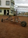
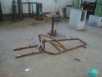
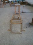
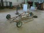
First try in making a Go-Kart

Status
Not open for further replies.

indianblood

New member
Messages
59
Reaction score
0
Location
Kolkata,India
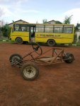
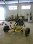
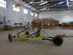
This is the first go-kart project am doing now,we don't get much of the instruments and tools here,so have to make adjustments.

there are 3 guys in our group who are making this go-kart.

I am enclosing the pictures of it for the time being,didn't get the engine now,will arrange it quite a few days
engine will be gear less (accelerator motion).


Have completed the chassis and the steering part of the vehicle.
I know that the wheelbase of the vehicle is big,but we made it but kinda estimating the length of the rider and other things,some of them could be mended later on.

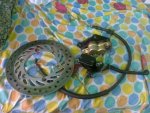
I have bought this disc brake setup,can anyone tell me how to operate the caliper of the master cylinder with a cable connected to the pedal(haven't made it though,was giving it a a thought)
will make a hub to hold the disc plate.

any other suggestion would be appreciated.
 

Attachments

  • 262032_2224224967774_1312244488_2631654_23860_n.jpg
    262032_2224224967774_1312244488_2631654_23860_n.jpg
    86.6 KB · Views: 95
  • 264178_2210377821604_1312244488_2610266_7162112_n.jpg
    264178_2210377821604_1312244488_2610266_7162112_n.jpg
    70.6 KB · Views: 60
  • 264252_2210378021609_1312244488_2610268_7258394_n.jpg
    264252_2210378021609_1312244488_2610268_7258394_n.jpg
    64.5 KB · Views: 52
  • 268294_2219324725271_1312244488_2625121_4029126_n.jpg
    268294_2219324725271_1312244488_2625121_4029126_n.jpg
    75.1 KB · Views: 836
  • 269782_2224224527763_1312244488_2631653_4019002_n.jpg
    269782_2224224527763_1312244488_2631653_4019002_n.jpg
    85.9 KB · Views: 88
  • 15072011215.jpg
    15072011215.jpg
    110.4 KB · Views: 56

Doc Sprocket

*********
Messages
15,677
Reaction score
151
Location
Ontario, Canada
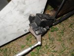
The simplest way to use that motorcycle master cylinder is to drill a hole in the handle and inch or so away from the handle pivot and attach a cable.

What I did, was to trace the handle onto paper, slightly redesign my tracing to suit my needs and eliminate all the extra handle length, and then cut the pattern out of 5/16" steel plate.

I'm about to take off for the weekend (no internet). If you want, I can provide more detail when I return. Here's a quick pic
 

Attachments

  • actuator.jpg
    actuator.jpg
    121.1 KB · Views: 69

indianblood

New member
Messages
59
Reaction score
0
Location
Kolkata,India
@toystory: thanks for your reply buddy,but I see that you have used solid bar to squeeze the brake fluid.
How can I setup a system with a cable? as i intend to put up the master cylinder and the caliper behind the rider,on the front part of the chassis

@landuse: thanks mate! :)
 

Doc Sprocket

*********
Messages
15,677
Reaction score
151
Location
Ontario, Canada
Sorry-I didn't have time to explain. Look closely at the picture- the long "bar" that you see is NOT a bar- it's a turnbuckle for adjusting cable tension. What you do not see in the picture is the cable that goes from the pedal to the turnbuckle.
 

bighead

New member
Messages
4,022
Reaction score
54
Location
Pacific Northwest USA
Great job you guys are doing on your kart. Is this a school project?

You may want to post a pic of your steering setup. The guys here are very good and getting your kart to drive right. Post a pic and it could save you lots of time and work later on friend.
 

indianblood

New member
Messages
59
Reaction score
0
Location
Kolkata,India
@bighead : we're in college,we had 2 months summer vacation and i was interested in making something related automobiles,so we made it.

Sorry now I cannot post a pic of the steering system now as the vehicle is in college workshop will upload the pic on Monday.
well we were having a little problem with the adjustment and alignment of the steering system.
 

bighead

New member
Messages
4,022
Reaction score
54
Location
Pacific Northwest USA
@bighead : we're in college,we had 2 months summer vacation and i was interested in making something related automobiles,so we made it.

Sorry now I cannot post a pic of the steering system now as the vehicle is in college workshop will upload the pic on Monday.
well we were having a little problem with the adjustment and alignment of the steering system.

Okay cool, I was looking at your tie rods. I think the pitman arm should be under the sterring column.
 

indianblood

New member
Messages
59
Reaction score
0
Location
Kolkata,India
@bighead: can you please explain what is pitman's arm and what is the use of it.

I am uploading the front view of the vehicle.


Attachments

  • 14072011210.jpg
    14072011210.jpg
    92 KB · Views: 769

Doc Sprocket

*********
Messages
15,677
Reaction score
151
Location
Ontario, Canada
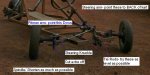
Also- your scrub radius is brutal. Cut the extra length off the front steering knuckles, and shorten those spindles as much as you possibly can.

EDIT- If you don't mind, I have several suggestions for you that will help create a better-performing frontend that will also be easier to apply the Ackermann Principle to.
 

Attachments

  • example2b.JPG
    example2b.JPG
    51.5 KB · Views: 129

indianblood

New member
Messages
59
Reaction score
0
Location
Kolkata,India
@toystory: I can shorten the spindle length,I guess i have to change the steering knuckle
I didnt get what you meant by point these to back of the kart about the steering arm and pitman arm this poin, both the tie rods are connected to a single point,had changed it after taking this pic.
I guess I will also change the tie rods,cant really level them right now,is that any problem?

Thanx for your valuable input!
 

Doc Sprocket

*********
Messages
15,677
Reaction score
151
Location
Ontario, Canada
It's not a matter of "you have to". More a matter if "it will work out better if you do".
As far as "pointing to the back" goes- I am referring to your steering arms. These are that point where the tie rods connect to the spindles. Looking at your kart, they point forward. This is fine. However, If you wish to apply the Ackermann steering principle, it's easier to accomplish if these arms point back instead of forward. Changing them around will also require you to point your pitman arm down, instead of up (check my diagram for terms). This should help level the tie rods out.
 

indianblood

New member
Messages
59
Reaction score
0
Location
Kolkata,India
The distance between the front wheels has been reduced quite a bit around 4-5"(dont remember the exact figure)

Lets see what kind of engine i get,will see if i can make an exhaust by myself.

Will surely keep that in mind to keep the engine centered

three of us were jumping on the vehicle to see if any weld breaks or not and surprisingly when another guy joined us nothing happened,thats >200 kgs,the shock absorbers were shocked

I know dynamicallyit will be different,but still!

well the engine will be mounted there,and if there is any problem regarding the rear chassis part,then we will change that,if we install the swingarm of Pulsar,it'll add up to the cost which we cant afford now,we want to keep the cost as minimum as we can,spent about 11k till now.

I know that the excessive length of the spindle arm will add up to the turning radius of the vehicle,but when we were riding it(guys pulling the cart) the turning radius was about 5-6 mtrs,is that too bad?

I was thinking about chopping off the excess,but havent done it yet,will install the engine and will see if its required or not.


TBH, the making of the spindle was purely was on the basis of gut feeling,so after making it,we changed it and I guess we have to change it again.we passed 1st year now in 2nd year and honestly dont have much technical knowledge or practical experience,we ourselves have made the whole blueprint of the cart,made it by our own hands(except welding of the chassis)
No help from teachers,seniors but internet!

We have a budget of 15k,can increase it, but our goal is/was

1.Should be light weight:roflol:
2.Even a layman can make it,maintain it.
3.Mileage will be maximum
4.Can carry load
5.Can be Raced:devil2:
6.Should be Cheap :ack2:


Attachments

  • 28072011255.jpg
    28072011255.jpg
    88 KB · Views: 628
  • 28072011254.jpg
    28072011254.jpg
    89 KB · Views: 629
  • 28072011256.jpg
    28072011256.jpg
    93.3 KB · Views: 621

bighead

New member
Messages
4,022
Reaction score
54
Location
Pacific Northwest USA
Lookin much better friend. I still would bring the spindles in. Less stress on the king pins as well. The kart will aslo ride better. And be much safer. Cut the extra off the bracke as well. Bring that wheel in as close as you can. I like your tie rods much better. Good job.

Does it tip over in tight turns? That might decide how the stance or wide it needs to be. T-Man did a trike thread. His tipped over on turn pretty easy. Have your buddies push you and do a tight turn.
 

redsox985

Active member
Messages
4,092
Reaction score
12
Location
PA
I think you're going to want to move the shock mount tabs closer to the cockpit. Once fully loaded, it's going to sag very low.
 

indianblood

New member
Messages
59
Reaction score
0
Location
Kolkata,India
Lookin much better friend. I still would bring the spindles in. Less stress on the king pins as well. The kart will aslo ride better. And be much safer. Cut the extra off the bracke as well. Bring that wheel in as close as you can. I like your tie rods much better. Good job.

Does it tip over in tight turns? That might decide how the stance or wide it needs to be. T-Man did a trike thread. His tipped over on turn pretty easy. Have your buddies push you and do a tight turn.

The steering is also working fine,didnt face much of a problem though.

Well,I suggested my group members the same,but they said that till now its working fine so if we see any problem in future we will just cut it out and modify it,our college vacations are over so,we get very little time to work on it.

Some of my mates were pulling and I was riding it,didn't feel that the vehicle was tipping over,maybe riding it at a speed will bring out some flaws.
The turning radius is around 5-6 mtrs.


I think you're going to want to move the shock mount tabs closer to the cockpit. Once fully loaded, it's going to sag very low.

Even I was thinking about the same,but for the time being,due to the shortage of time we'll just let it be there.

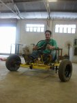
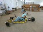
Well here's a pic of a group member sitting on it.


Attachments

  • 28072011258.jpg
    28072011258.jpg
    81 KB · Views: 581
Status
Not open for further replies.
Top