Experimental tubing bender from a 20HP engine

gegcorp2012

Active member
Messages
491
Reaction score
62
Location
Alabama
Not using as a tool yet, but hopefully will make a demo video if it works as expected.

I'm attempting to make a gear driven tubing bender out of a tired old engine.

Here's where I got the idea:

I found a couple of YT videos the other night where people have made gear driven metal benders using a flywheel and starter gear, or a gear set and sturdy bearings. One video the builder used a lathe to turn a set of mandrels and I like the idea of having interchangable mandrels, but got no lathe. (I think his channel is MeanWhile in The Garage)
Screenshot_20210114-095247.jpg
This setup bends square tubing and is capable of making an "S" shape bend.

The other video (in Russian(?)) shows making a bender out of gears and bearings.

He is bening round tubing, and showed how he made a mandrel adapter. This setup can also be used to bend flat stock edge-wize and I was really impressed by the minimal simplicity of that design.

I want to take some of their ideas and apply it to one of my own... to use an old engine (Kohler SV600) to see if I can make a DIY bender without access to a lathe or spending lots of money.

Here's how far I got tonight:
Started with a really dusty engine that had a sticking exhaust valve. Engine was purchased for 30 cents a pound at the scrap yard... about $24 bucks.

I took the case apart and took out the crank for a couple of modifications.
I removed the huge balancer weights and cut the crank snout so it does not go past the bottom of the case.

20210116_205807.jpg 20210116_213558.jpg20210116_225418.jpg
20210116_215944.jpg

Also took out the cams and left out the rod and piston and head since they are not needed.

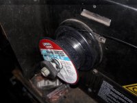
Here it is all back together, with some 5/16" or ~8mm thick flat bar and some 1/4" or 6.35mm thick angle iron because those are the heaviest pieces I have my stock pile.
20210116_224350.jpg
I think I will use the cylinder head area to mount some kind of feed roller for the work piece.

I plan to make some mandrels that will bolt onto the flywheel and try to use the flat spot where the ignition pickup was mounted to hold the stationary end of the work piece.

I will use the opposite side of the case where there are a couple of case bolts with flat space in between to mount the starter wheel (drive gear) in between.

At least that's the plan for now.
 
Last edited:

gegcorp2012

Active member
Messages
491
Reaction score
62
Location
Alabama
I finished a couple of modifications to the flywheel and engine block. Just had to grind off the high spot where the ignition magnet mounted and take down a couple of bosses on two bolt holes on the case.

20210117_194136.jpg 20210117_195401.jpg

I found a large bearing out of the Yamaha 350 axle carrier and used it for the drive pulley mount. I welded the starter gear to the inner race of tge bearing, Then I took the crank snout that I had cut off and put it on top of the starter gear.
20210118_122213.jpg 20210118_132959.jpg
I made a mounting plate to go over the cylinder head because that part of the block seems to be strongest. Used angle iron and flat plate.
20210118_112741.jpg 20210118_120749.jpg
Made some mounting tabs and drilled for bolts to hold the plate into place.
20210118_212545.jpg

Made a crank handle from the pulley shaft and a piece of pipe, then tried the first strength test... bending some 1/2" rebar...

20210118_213041.jpg 20210118_213228.jpg

It works (on rebar).

I need to mount a brake rotor (from a 93 Passat) to the flywheel next to have a better work surface for holding the work piece and make a mandrel attachment for round tubing.
20210118_213629.jpg
I plan to order an new rotor, so that will be 10 bucks. I have less than $50 US and less than 8 hours invested in this project.
 
Last edited:

gegcorp2012

Active member
Messages
491
Reaction score
62
Location
Alabama
I got a new rotor since the rusty one is used as a tarp weight to hold the cover on a mower.

Just 12 bucks for the new rear rotor.

20210123_194754.jpg
I cut the top off of the Roto where the lugs go through, then tacked it onto the flywheel. I used (3) .75" nuts to center the rotor to a circular lip on the flywheel.

Screenshot_20210123-212407.jpg


20210123_211805_1.gif

Now that that I have the nice surface of the new rotor to compare to, I can see the drive crank shaft was welded on a bit crooked.

Couldn't help but try it anyhow....
Black steel pipe was starting to bend but the vice grips bent too and let go !
20210123_211714.jpg

Need to make a proper workpiece holder now.
 
Last edited:

gegcorp2012

Active member
Messages
491
Reaction score
62
Location
Alabama
Thanks @Karts of Kaos

I added the workpiece clamp and it seems to hold much better.
20210125_194617.jpg 20210125_225434.jpg 20210125_225516.jpg

Then I tried to bend a piece of square tubing and the weld holding the short piece of crankshaft to the starter drive gear snapped.
20210125_230631.jpg 20210125_231525.jpg

I was expecting the bearing may pull loose or break first.

When welding the 2"x1/4" workpiece clamp to the rotor, the welder was having a wire feed issue where it would run a second then slip a second then repeat. That turned out to be the tensioner was too tight , so I fixed it with a jamb nut... also noticed I'm running out of flux core wire, so I went ahead and got a new tank of welding gas and will switch to solid core wire to see if that helps.
 

Attachments

  • 20210125_225600.jpg
    20210125_225600.jpg
    2.3 MB · Views: 2

gegcorp2012

Active member
Messages
491
Reaction score
62
Location
Alabama
Got a roll of MIG wire today to re-weld the drive crank piece.

First I used the grinder to extend the key slot on the crank snout so I could flip that piece over and slip the driver handle on.
20210130_103806.jpg

I had to make the hole in the starter gear one size bigger to fit the bolt for the squarely machined end of the crank snout.
20210130_103945.jpg

Then drill-hacked a hole in the back of the bearing mounting plate so I c a socket to tighten the crank bolt.
20210130_105144.jpg

Then I snugged up the starter gear to the crank snout piece.

20210130_105135.jpg

Then I welded the starter gear to the crank snout. I get much better welds with gas than with the flux core wire.

I ran outside and put some lag bolts in a stump to hold the crankcase while I turned the handle around.
20210130_183148.jpg

Here is a bend on a piece of 1.04" (26. mm) tubing. wall thickness is .007" (1.8 mm)
Screenshot_20210130-174359.jpg

This 270 degree bend has a 6" inside diameter and was made without a mandrel - so the tubing has flat spots in it but it did not pinch and collapse. One end was in the holding clamp and the workpiece was drawn over the flat surface of the brake rotor and fed in by the crank snout

20210130_173215_1.gif
20210130_173624.jpg 20210130_192747.jpg
 
Last edited:

gegcorp2012

Active member
Messages
491
Reaction score
62
Location
Alabama
thats awesome!
Thanks @Budget GoKart . Still have some work to do on mandrels so I can get better bends without flattening the tubing.

I added some brackets on the bottom. of the engine block so I can bolt it to the work bench.
20210206_110324.jpg 20210206_120700.jpg
Before bending the piece of 1-1/4" (32mm) tubing, I carved up a piece of 1" (24mm) tubing and ran it through the bender.

20210206_160441.jpg
I ran out of leverage with the pulley handle when working on the bench and decided to switch over to a ratchet drive.

20210206_165340.jpg
A 17mm 1/2" drive socket is the same OD as the drive shaft, so I used a cutoff wheel to whittle a 17mm hex head from the end of the drive shaft.

I used the big torque wrench to find out it takes ~140 ft/lb of input torque to get the bend going on the 31mm tube... then something popped.
20210206_165754.jpg 20210206_175717.jpg
It was the starter gear <again>. The gear is some kind of alloy that does not hold a weld. The weld rips out.

So, I had to open up the
back of the bearing plate and get in to weld the bottom of the sprocket again.

Decided to go around the edge of the bearing again, then make cover up the bolt head in molten metal this time...
20210206_153539.jpg 20210206_171808.jpg

After cooling a bit, I re-assembled everything and started cranking away on the 1-1/4" tube again until it kinked.
20210206_173059.jpg

Now I'm back where I started, but with a sturdily mounted bender that has a stronger and easier to use drive.

The workpiece holder is doing it's job
20210206_173121.jpg
Still need to make some mandrels to mess with the thin wall tubing...

I think I will try to bend some pipe to see if anything else breaks before making mandrels.
 

gegcorp2012

Active member
Messages
491
Reaction score
62
Location
Alabama
Break and fix <again>.

I kind of knew I would regret this test - trying to bend a piece of 24mm x 3mm pipe. You can see a slight bend was all I got too.
20210208_204422.jpg
I had to crank up the torque past 150 ft.lb. and stood firmly when pulling on the ratchet with a cheater pipe... then something else popped.

20210208_134936.jpg
Some of the welds on the outer bearing race let loose. (originally welded with flux core wire, trying not to melt the bearing race).

Also noticed some small pieces of metal flew up, as the face of three of the drive gear teeth flaked off. After taking the bearing plate off, I could see it had flexed and bent upward underneath the flywheel area where there are no fasteners to hold it down.

20210208_134808.jpg

So, I ground the bearing off the plate and made a bigger hole to fit the bearing inside the plate and give additional clearance do the flywheel don't chew up the bottom of the drive sprocket.
20210208_190054.jpg 20210208_191731.jpg 20210208_191741.jpg

Much better welding with gas, and I went all the way around the bearing and put a thin bead on the other side for good measure.

Then I cut a piece of 1/4" thick scrap to weld on the end of the bearing plate to keep it from flexing.
20210208_192714.jpg
Battery was dead on my phone, so no picture of the brace improvement.
 

gegcorp2012

Active member
Messages
491
Reaction score
62
Location
Alabama
Working out the kinks! (y)
Exactly.
My short term plan is to use this bender
to make pieces for my hydraulic bender.

I will have to rework that one to handle 1.5" tubing for buggy project.

None of my tools can make perfectly smooth bends in any size tubing today
 

JTSpeedDemon

2019 Build Off Winner!
Messages
4,026
Reaction score
147
Location
Texas
Haha build a bender to make a better bender. Welcome to the path of industry! :lolgoku:
But seriously that's really cool that you're building tools to build tools, that's how mankind got to where we could have go karts!
 

gegcorp2012

Active member
Messages
491
Reaction score
62
Location
Alabama
Some progress.... Here are some bends on some stock that I am using to make a new set of dies for my hydraulic bender.

The spiral bend is on 1.5" x 3/16" (38 x 4.6 mm) flat bar and the 90 degree turn is on 1" x 3/16" (25 x 4.6 mm) flat bar.
20210213_095755.jpg

I had to use the hammer to flatten the 90 degree bend, so I am making the flat guide that is required for bending across the width of flat stock.
 
Top