Electric component ratings AC vs. DC

Status
Not open for further replies.

Functional Artist

Well-known member
Messages
5,497
Reaction score
3,079
Location
Toledo, Ohio
Connector/Receptacle Housings

Now, lets discuss electrical connector housings
...their "basically" just insulators too.
(it's the box or container that holds & insulates the terminals, contacts/conductors or fuse from...everything)

The "housings" on most crimp-on terminals, connectors, receptacles, switches & even fuse holders have plastic "looking" housings
…& some are made out of rubber, but we'll cover that later. :cheers2:

Most housings are "usually" not just plain old plastic
...some of the white ones, like the Molex type, are actually nylon with a flammability rating of 94V-2 & an (operating) temperature range of -40* - +105*C.
https://www.molex.com/webdocs/datasheets/pdf/en-us/1501761020_CRIMP_HOUSINGS.pdf

But, some like the XT type connectors use what's referred to as high-temp nylon.
(makes sense, a higher amperage connector would need/use a higher temp rated housing)
https://www.sparkfun.com/products/10474

...& then, some housings like fuse holders & receptacles use (black) thermoplastic UL 94-V2 with the same (operating) temperature range of -40* - +105*C.
https://media.digikey.com/pdf/Data Sheets/Littelfuse PDFs/153 inline fuseholder.pdf


But, again many of these components don't have any type of "actual" ratings marks or labels.

Like, for example, your average fuse holder (round or blade)
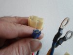
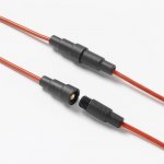
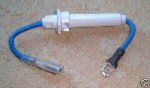
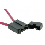
...like in pics #2, 3, 4 & 5 below. (their are no visible markings, of any kind)

So, then, were back to
...are there any indicators?
…& what do they tell us?

First, since they are all electrical components, are we "safe" to assume that they all would have at least a "standard" UL 94-V2 (-40* - +105*C) temperature rating?
...or how about the size of the contacts?
...or the size (gauge) of wire that is attached?
...or the size & type of fuse that it's designed to hold?
...any other clues, like look & feel or "quality/craftsmanship" of the component?

IMO
Yes, their are indicators. :thumbsup:
...they don't tell us everything, but add more pieces to the puzzle.

It would make sense to make all electrical component housings meet the "standard" UL 94-V2 temperature rating.

As for the size of the contacts, if we compared them to the Namz & Molex connectors specs, ~2mm contacts = (up to ~10A) & ~4.5mm contacts = (up to) ~20A

The gauge of wire used tells us, 18-20g. is usually good for (up to) ~5A, 14-16g. is usually good (up to) 10A & 10-12g. is usually good (up to) 20A

The size of the fuse doesn't help much because most of them range anywhere from ~1A thru ~40A

Visual & physical quality
...do the terminals fit tightly?
...is the housing molded cleanly or sloppily?

These are all indicators (& their may be more) as to the potential usability of a component.
:2guns:
 

Attachments

  • SAM_4170.JPG
    SAM_4170.JPG
    1.3 MB · Views: 0
  • Littelfuse_Fuse_Holder_150_Image_jpg.jpg
    Littelfuse_Fuse_Holder_150_Image_jpg.jpg
    69.3 KB · Views: 0
  • s-l1000.jpg
    s-l1000.jpg
    16.7 KB · Views: 0
  • thLM4945WA.jpg
    thLM4945WA.jpg
    6 KB · Views: 35
  • SZ2045ImageMain-515Wx515H.jpg
    SZ2045ImageMain-515Wx515H.jpg
    31 KB · Views: 0

Functional Artist

Well-known member
Messages
5,497
Reaction score
3,079
Location
Toledo, Ohio
Temperature Ratings & Heat Build-Up

Let's get back to the temperature (heat build-up) part of the equation. :thumbsup:

First,
Keep in mind that temperature issues usually affect the insulators. (wire coverings & switch/connector housings) Not the conductors (wires & terminals) themselves.

Second,
Is it an Intermittent Duty or Constant Duty situation?
If a circuit is only used for an intermittent purpose, like to activate a horn or the reverse function, then there is a "lot less" chance of any heat building up, in any of the electrical components in the circuit.

During an average ride the current would only be flowing thru, the components used in the circuit, for a brief amount of time & there's just not very much time for any heat to build up.
(How often do ya use the horn or reverse?)

But, if the circuit is used for a constant duty purpose, like to turn/switch a speed controller on, then ALL of the components used in that circuit must be able to handle any heat that would/could build up.
Because current would be flowing thru the component used in this circuit, the whole time that the circuit is on, there's a lot more time for (damaging) heat to build up.

So, when factoring "heat build-up" in the equation, it seems that on intermittent duty circuits we have a bit more "flexibility"
...but, on the constant duty circuits it would be BEST to only use "properly" rated components.


So, where does the heat (in a circuit) come from?
(the Voltage?...the Amperage)
Nope, (from what I understand) it's from the resistance (in the circuit)

Here is some info I found on resistance

Resistance
The electrical resistance of an object is a measure of its opposition to the flow of electric current. The inverse quantity is electrical conductance, and is the ease with which an electric current passes. Electrical resistance shares some conceptual parallels with the notion of mechanical friction. The SI unit of electrical resistance is the ohm (Ω), while electrical conductance is measured in siemens (S).

The resistance of an object depends in large part on the material it is made of—objects made of electrical insulators like rubber tend to have very high resistance and low conductivity, while objects made of electrical conductors like metals tend to have very low resistance and high conductivity. This material dependence is quantified by resistivity or conductivity. However, resistance and conductance are extensive rather than bulk properties, meaning that they also depend on the size and shape of an object. For example, a wire's resistance is higher if it is long and thin, and lower if it is short and thick. All objects show some resistance, except for superconductors, which have a resistance of zero.
The resistance (R) of an object is defined as the ratio of voltage across it (V) to current through it (I), while the conductance (G) is the inverse.

For a wide variety of materials and conditions, V and I are directly proportional to each other, and therefore R and G are constants (although they will depend on the size and shape of the object, the material it is made of, and other factors like temperature or strain). This proportionality is called Ohm's law, and materials that satisfy it are called ohmic materials.

Static and differential resistance
There are two types of resistance:
Static resistance (also called chordal or DC resistance) – This corresponds to the usual definition of resistance; the voltage divided by the current. It is the slope of the line (chord) from the origin through the point on the curve. Static resistance determines the power dissipation in an electrical component. Points on the IV curve located in the 2nd or 4th quadrants, for which the slope of the chordal line is negative, have negative static resistance. Passive devices, which have no source of energy, cannot have negative static resistance. However active devices such as transistors or op-amps can synthesize negative static resistance with feedback, and it is used in some circuits such as gyrators.
Differential resistance (also called dynamic, incremental or small signal resistance) – Differential resistance is the derivative of the voltage with respect to the current; the slope of the IV curve at a point.

Energy dissipation and Joule heating
Resistors (and other elements with resistance) oppose the flow of electric current; therefore, electrical energy is required to push current through the resistance. This electrical energy is dissipated, heating the resistor in the process. This is called Joule heating (after James Prescott Joule), also called ohmic heating or resistive heating.

The dissipation of electrical energy is often undesired, particularly in the case of transmission losses in power lines. High voltage transmission helps reduce the losses by reducing the current for a given power.

On the other hand, Joule heating is sometimes useful, for example in electric stoves and other electric heaters (also called resistive heaters). As another example, incandescent lamps rely on Joule heating: the filament is heated to such a high temperature that it glows "white hot" with thermal radiation (also called incandescence).

The formula for Joule heating is:
(P = I (2) R ) where P is the power (energy per unit time) converted from electrical energy to thermal energy, R is the resistance, and I is the current through the resistor.
https://en.wikipedia.org/wiki/Electrical_resistance_and_conductance

Here is another way of putting it :cheers2:

"The simplest way of thinking about resistance is that the current carrying electrons are colliding with the atoms that make up the conductor. By collide I mean the electrons can interact with the atoms via the Coulomb force.

The kinetic energy of the electrons is transformed into vibrational energy of the atoms. As you should know temperature is just vibrational energy, so energy lost from resistance will heat up the conductor."
https://physics.stackexchange.com/q...eally-is-resistance-how-does-it-generate-heat

Here is some info I found on overheating.

Overheating of electrical circuits
"Overheating is a phenomenon of rising of temperature in an electric circuit (or portion of a circuit). Overheating causes potential damage to the circuit components, and can cause fire, explosion, or injury. Damage caused by overheating is commonly irreversible; i.e. the only way to repair is to replace some components.

Cause
On overheating, the temperature of the part rises above the operating temperature.
Overheating can take place
1.if heat is produced in more than expected amount (such as in cases of short-circuits, or applying more voltage than rated), or
2.if heat dissipation is poor, so that normally produced waste heat does not drain away properly.

Overheating may be caused from any accidental fault of the circuit (such as short-circuit or spark-gap), or may be caused from a wrong design or manufacture (such as the lack of a proper heat dissipation system).

Due to accumulation of heat, the system reaches to an equilibrium of heat accumulation vs. dissipation, at a much higher temperature than expected.

Proper (procedure) manufacture
For a certain definite purpose in a definite electrical equipment or a portion of it, definite type and size of materials (for boards, wires, insulators) with proper rating for voltage, current and temperature, are used. The circuit-resistance never kept too-low. To prevent short-circuit, on the wire-joints, appropriate type of electrical connectors and mechanical fasteners used. "
https://en.wikipedia.org/wiki/Overheating_(electricity)

This is why it's so very important that the temperature ratings of ALL components used in a circuit meet or exceed any potential temperature that could build-up in the circuit.
 

Functional Artist

Well-known member
Messages
5,497
Reaction score
3,079
Location
Toledo, Ohio
You can't judge a book by it's cover

When dealing with "electrical" components, it's about the same concept.

You can't always tell what's going on inside by just looking at the outside. (yea, I know that's what Sid said) :thumbsup:

Unless you disect 'em, that is. (Sid may have said this too) :lolgoku:

For example, (10) different switches could look alike from the outside
but, inside they may have
...a different "action" design (slow break or fast break)
...or a different contact style (single brake or double brake contacts)
...or the contacts are spaced further apart when opened (like 3mm or 5mm)
...or what the contacts are made of (copper, brass, gold plated etc.)
...or the size of the contacts (like 2mm or 4.5mm)
...or if it even functions
(many times a non-functioning or burned out switch (most electrical components) looks & acts just like a normal/functioning switch)
...except for the part where it don't work :ack2:

So, what do the exterior indicators, on a switch, tell us?

Bigger switch = higher amp ratings? not always
The size of a switch may be determined by where it need to fit in a specific application.


Bigger terminals = higher amp ratings? yes, but
The size of the terminals indicate what amps the "terminals" themselves can handle.
...but, doesn't really tell anything about the other parts of the switch


Example: a 10A switch with spade terminals would have 4.5mm spade terminals, that can handle 10A.
…but, a 5A rated switch with spade terminals may also have the same 4.5mm spade terminals.

False indicators? No
This just tells us that both switches were designed to work with "standard" 4.5mm spade terminals & their mating counterparts.

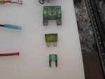
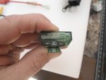
Blade style fuses would be another good example.
A mini blade fuse (rated 30A) has ~3mm x ~1mm conductors/contacts
A med blade fuse (rated 30A) has ~5mm x ~1mm conductors/contacts.
A maxi blade fuse (rated 30A) has ~8mm x ~1mm conductors/contacts.

That's (3) vastly different sized fuses with the exact same rating.
...but, they are for (3) vastly different applications/situations.

So, we just have to keep in mind that the component/circuit designer may have used/incorporated things in an electrical component for ulterior purposes. (fit & usability NOT to indicate or handle a certain capacity)
 

Attachments

  • SAM_4158.JPG
    SAM_4158.JPG
    1.3 MB · Views: 0
  • SAM_4160.JPG
    SAM_4160.JPG
    1.3 MB · Views: 0

Functional Artist

Well-known member
Messages
5,497
Reaction score
3,079
Location
Toledo, Ohio
Did someone say dissecting?

Been doin some comparin', of different components
...some switch dissectin'
…some housing meltin'
…& some thinkin' about temperature ratings

Dissecting
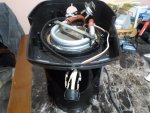
First I removed the on/off switch out of an old Mr. Coffee coffee maker
Printed on the side of the switch is:
3510 100-125V

Molded on the side is:
16A 125VAC 10A 250VAC
10A 24VDC 3/4HP 250VAC
T105 1/2 HP 125VAC

Visually
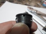
It looks to be just a rocker type switch in a black plastic (probably thermoplastic) "cup" style housing with (3) ~4.5mm spade style conductor/contacts protruding out of the bottom.

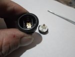
Took 'er apart :thumbsup:
Inside there are just a couple of contacts & a small LED light in the rocker/lever.

Melting stuff
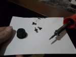
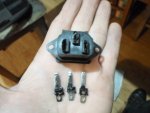
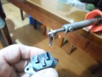
Next, since I have some C-14 receptacles/connectors, I won't be using, lets see how fast the housing fails or "gives up" when the conductor is heated up.
(I figured "standard" soldering iron temp (~600*) would be more than enough)

Yup, the conductor heated up really quick (~5-10 seconds)
...& the housing failed (almost) immediately. :smiley_omg: (the conductor just slid right out)
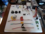
I really don't think a DC rated C-14 connector would have withstood that temp any better

Comparative testing
So, to test this theory I performed the same test on the conductor/terminals of the switch.

Yup, it failed just as quick. :ack2:

Then, taking it a step further, if ya remember the operating temp of many "Nylon" connectors (like Molex & Namz) & even the thermoplastic ones is -40C - +105C.

This seems to indicate that -40C - +105C are the "standard" operating temperature parameters for most ELV (extra low voltage) DC (direct current) circuits.

So, looking at the conductors/connectors on an "average" AC rated C-14 connector
(like the one tested/dissected above)

(If we were gonna use 'em but, we are NOT)
...it looks like the conductors could/should easily handle the requirements for small (ELV) battery chargers.

Voltage 60VDC (up to 72VDC)
…& the amperage (~2.5A)
…& with a the temp rating is 70*C (158*F) :2guns:
 

Attachments

  • SAM_4280.JPG
    SAM_4280.JPG
    1.3 MB · Views: 1
  • SAM_4273.JPG
    SAM_4273.JPG
    1.3 MB · Views: 1
  • SAM_4270.JPG
    SAM_4270.JPG
    1.3 MB · Views: 1
  • SAM_4269.JPG
    SAM_4269.JPG
    1.3 MB · Views: 1
  • SAM_4151.JPG
    SAM_4151.JPG
    1.3 MB · Views: 4
  • SAM_4324.JPG
    SAM_4324.JPG
    1.2 MB · Views: 0
  • SAM_4318.JPG
    SAM_4318.JPG
    1.2 MB · Views: 0
  • SAM_4232.JPG
    SAM_4232.JPG
    1.2 MB · Views: 1
  • SAM_4225.JPG
    SAM_4225.JPG
    1.2 MB · Views: 1

Functional Artist

Well-known member
Messages
5,497
Reaction score
3,079
Location
Toledo, Ohio
More component dissections/comparisons

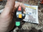
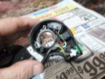
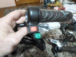
For comparison purposes I ordered & dissected a "cheep" Chinese combo 3-way switch. (~2.00)
It has an On/Off switch (for like a headlight), an On/Off/On switch (like for turn signals) & a push button switch (like for a horn).
It's made for mounting on the handle bars of bicycles, scooters & such, kinda like a throttle.


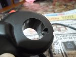
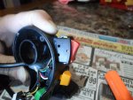
First thing I noticed was the thin (flimsy) plastic housing.
The mechanical connection (where the switch mounts to the handle bars) is ALL plastic too. It doesn't even have a metal clamp ring insert like most throttle/switches do, just a "set screw".

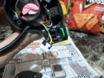
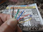
Second thing was the (thin) ~22g. wires used in the wiring harness.
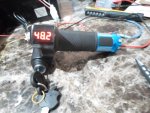
The wires used on ALL (5) of the throttles I tested all had (larger) ~18g. wires.

Third was the (generic) switches.
They seem to have a simple design, very small connecting terminals & NO ratings listed anywhere.

So, it's pretty easy to see comparing this "cheep combo" switch to one (any one) of the throttles used on these go karts/scooters & there are a few big differences.

IMO this "cheep combo" switch seems to be basically designed for bicycles. Not really electric powered (24V - 72V) bikes, just bicycles in general. Like for 12V accessories.
…& even @12VDC I would be kinda skeptical of running very much amperage thru it.
:ack2:
 

Attachments

  • SAM_4074.JPG
    SAM_4074.JPG
    1.3 MB · Views: 0
  • SAM_4080.JPG
    SAM_4080.JPG
    1.2 MB · Views: 0
  • SAM_4093.JPG
    SAM_4093.JPG
    1.3 MB · Views: 0
  • SAM_4085.JPG
    SAM_4085.JPG
    1.3 MB · Views: 0
  • SAM_4084.JPG
    SAM_4084.JPG
    1.3 MB · Views: 0
  • SAM_4082.JPG
    SAM_4082.JPG
    1.3 MB · Views: 0
  • SAM_4070.JPG
    SAM_4070.JPG
    1.3 MB · Views: 0
  • SAM_3507.JPG
    SAM_3507.JPG
    1.3 MB · Views: 0
  • SAM_3522.JPG
    SAM_3522.JPG
    1.3 MB · Views: 0

Functional Artist

Well-known member
Messages
5,497
Reaction score
3,079
Location
Toledo, Ohio
More info, kinda sums it all up. :cheers2:

"When designing for a 60 volt circuit, engineer a safety margin of 1.3 to 1.5 times the minimum requirements. 60 volts at 1.3 times is 78 volts. 72 volts is close enough and you shouldn't encounter any problems.

When designing for a 10 amp system, engineer in a safety margin of 1.3 to 1.5 times the minimum requirements. 10 amps at 1.3 times is 13 amps. At 1.5 times that's 15 amps. Your 72 volt 15 amp switch would be just fine.

When designing a system, engineer in a safety margin of 1.5 to 2 times the minimum wattage. If your system draws 600 watts you want to plan on 900 to 1200 watts.

Follow those practices and you'll never have an issue. Even if you don't know the ratings on Chinese switches, the math is not that hard. Since you're talking about a control circuit it's very likely you'll have very low currents." Tonyr1084


Definitive info & a logical path/practice to follow, I love it! :2guns:
 
Status
Not open for further replies.
Top