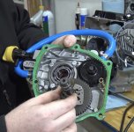
Designing a connecting rod, I'd love some insights on how stock rods fail etc.

busted_blocks

Active member
Messages
110
Reaction score
99
Location
Dongguan, China
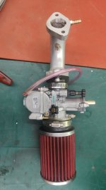
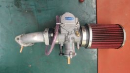
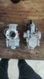
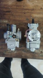
Seeing as anything below PWK28 is NOT a genuine PWK (Keihin) it could be a cheap bad copy, or it could be that you don't have a background in engines.

There are cheap problematic copies, and there are those that just need a little help to be what they pretend to be but since you are trying to use a motorcycle carburetor in a nonstandard application... of course it's not going to work worth a damn if you don't put in the work.

The simplest thing you can do is double check the float hight and check the enrichment plunger for debris and being loose. The enrichment circuit is an easy corrected common issue with those carbs

I run a PWK24 on my 208 and I don't have those issues but that engine is pretty far from stock too.
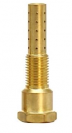
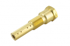
Emulsion tube drilled
2t Power jet deleted
Lots of hours dialing it in
I'm not good at carburetors, that's true. I got a PE22 dialed in pretty well for a previous engine, but these PWK's I just can't seem to lean out, no matter what I do. The PE22 was a super cheap copy and leaks terribly, so I was trying to get better carbs. I've tried PWK21, and several PWK24s. I'm also not buying the cheap copies, but the expensive copies. I've also got them from 2 suppliers. I'm not saying the carbs are not the issue but it's odd. I have an oxygen sensor on the exhaust and it just won't seem to go about 12:1. The smallest pilot I have is 32, I saw some 30s out of stock but the store says 38 should be the right one.

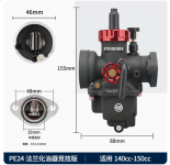
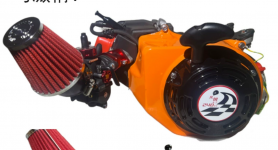
The carb I probably should have bought was the Nibbi racing PE22/24, I have that brand on my dirt bike. It's also the stock carb for the 240CC briggs copy(I think that's what they copied anyway) they sell here. I haven't bought it because it's pretty expensive, but there is something to be said for you get what you pay for.
 

Attachments

  • nibbi.png
    nibbi.png
    506 KB · Views: 3
  • 240cc.png
    240cc.png
    573.5 KB · Views: 3
  • pwk4.jpg
    pwk4.jpg
    1.1 MB · Views: 3
  • pwk3.jpg
    pwk3.jpg
    1.1 MB · Views: 2
  • pwk2.jpg
    pwk2.jpg
    1.1 MB · Views: 2
  • pwk1.jpg
    pwk1.jpg
    1.1 MB · Views: 2
Rat

Well-known member
Messages
1,750
Reaction score
1,298
Location
SW Virginia
I'm not good at carburetors, that's true. I got a PE22 dialed in pretty well for a previous engine, but these PWK's I just can't seem to lean out, no matter what I do. The PE22 was a super cheap copy and leaks terribly, so I was trying to get better carbs. I've tried PWK21, and several PWK24s. I'm also not buying the cheap copies, but the expensive copies. I've also got them from 2 suppliers. I'm not saying the carbs are not the issue but it's odd. I have an oxygen sensor on the exhaust and it just won't seem to go about 12:1. The smallest pilot I have is 32, I saw some 30s out of stock but the store says 38 should be the right one.
First and foremost the "correct one" cannot be determined without knowing the engine its going on, and the altitude it will operate at, and even then there are other factors that change the should be range.

A straight pipe exhaust, especially a stepped diameter one will typically lean it out.

You need to get a welding tip drill set (a hand drill with extremely tiny bits including 026, 030, 035, and 040) and start by reaming a few of the upper emulsion tube air bleed holes to lean the low side out.

The fact that a #32 isn't small enough is a telltale sign you have a problem either with the carb, the valves, or the exhaust and excessively restricted air filter combined with an overly restricted exhaust will be too rich to run.

I still suggest unscrewing the enrichment assembly and making sure there's nothing that could be holding it open, just be easy it's only plastic.
 

Rat

Well-known member
Messages
1,750
Reaction score
1,298
Location
SW Virginia
I forgot to add that I run a PWK24 on my 208 with a #48 pilot (iirc I know it's in the 40's) and a #125 main.
I've got a velocity stack with a low resistance cotton cover over it's screen, a 3 diameter step custom long exhaust and silencer. It starts at 1" OD to clear the studs, and steps to 1" ID ahead of the first bend, steps to 1¼ after the second bend, with the final diameter step being the custom 2¼ OD slip on 2 piecce silencer I made which can be ran as a baffle only, or packed to achive the desired amount of noise deadening.
 

busted_blocks

Active member
Messages
110
Reaction score
99
Location
Dongguan, China
First and foremost the "correct one" cannot be determined without knowing the engine its going on, and the altitude it will operate at, and even then there are other factors that change the should be range.

A straight pipe exhaust, especially a stepped diameter one will typically lean it out.

You need to get a welding tip drill set (a hand drill with extremely tiny bits including 026, 030, 035, and 040) and start by reaming a few of the upper emulsion tube air bleed holes to lean the low side out.

The fact that a #32 isn't small enough is a telltale sign you have a problem either with the carb, the valves, or the exhaust and excessively restricted air filter combined with an overly restricted exhaust will be too rich to run.

I still suggest unscrewing the enrichment assembly and making sure there's nothing that could be holding it open, just be easy it's only plastic.
I have all those drills, so no issue there. I can drill out some of those holes in the emulsion tube.

It's possible it's the valves, though I have this issue with at least 3 different heads. The head that's on this engine is heavily modified, but likely max restriction is the intake runner as my work was confined to larger valves and rounding out the step in the bowl + removing sharp edges. On this last run there was oil in the chamber. I think the head was possibly not sealed properly. The block was decked, and it's possible the stock dowel pins used for the head alignment were a bit long. I ground those down, so if that was a problem, it won't be next time.

Exhaust is very close to straight pipe. There is a section of rolled corrugated steel in the exhaust but it's of much larger diameter than the pipe. There is a tight bend where the exhaust comes off the header, but again it should be relatively free flowing. I even machined the flange flat to help ensure a good seal with the gasket. Air filter looks to be free flowing, but I have no tests to back that up.

I will definitely unscrew the enrichment circuit and have a look.

Thanks for the suggestions. I'll keep working on it. My goal is to make a reliable 15HPish engine and learn what I'm doing along the way.

This build is currently "stock" timing, but I don't know what that is yet. GXV160 aluminum fly wheel, about 10.5:1 compression, dished piston, decked block (.035"), 15CC head with 30.5in/27ex valves, 0.052" head gasket, mildly ported to remove sharp edges. Stock rod with that scoop, stock cam, stock springs. I was planning to change the timing after break-in. All assembled with studs.
 

Attachments

  • pipe4.jpg
    pipe4.jpg
    1.1 MB · Views: 4
  • pipe5.png
    pipe5.png
    595 KB · Views: 4

busted_blocks

Active member
Messages
110
Reaction score
99
Location
Dongguan, China
I forgot to add that I run a PWK24 on my 208 with a #48 pilot (iirc I know it's in the 40's) and a #125 main.
I've got a velocity stack with a low resistance cotton cover over it's screen, a 3 diameter step custom long exhaust and silencer. It starts at 1" OD to clear the studs, and steps to 1" ID ahead of the first bend, steps to 1¼ after the second bend, with the final diameter step being the custom 2¼ OD slip on 2 piecce silencer I made which can be ran as a baffle only, or packed to achive the desired amount of noise deadening.
Any chance you can dig up a picture of that exhaust? I'd love to take a look. Sounds great
 

Rat

Well-known member
Messages
1,750
Reaction score
1,298
Location
SW Virginia
I have all those drills, so no issue there. I can drill out some of those holes in the emulsion tube.

It's possible it's the valves, though I have this issue with at least 3 different heads. The head that's on this engine is heavily modified, but likely max restriction is the intake runner as my work was confined to larger valves and rounding out the step in the bowl + removing sharp edges. On this last run there was oil in the chamber. I think the head was possibly not sealed properly. The block was decked, and it's possible the stock dowel pins used for the head alignment were a bit long. I ground those down, so if that was a problem, it won't be next time.

Exhaust is very close to straight pipe. There is a section of rolled corrugated steel in the exhaust but it's of much larger diameter than the pipe. There is a tight bend where the exhaust comes off the header, but again it should be relatively free flowing.
That corrugated crap is more restrictive than you'd expect, and extremely prone to plugging up.

Just because it seems free flowing, doesn't mean it really is under pressure, the tighter the bends the worse the pressure bottle neck will be at the bend.
Any chance you can dig up a picture of that exhaust? I'd love to take a look. Sounds great
Not a good one, but I've got a new chain to install and it will need to come off for room to see WTF I'm doing so I can get some.
It's not particularly a pretty pipe, but the diameter changes help keep the backpressure down.

As for the emulsion tube, don't just go hogging it out all willy-nilly.
Figure out which bit fits without snagging or wiggling and document the size.
The most common Etube configuration is 2 or 4 fueling holes isolated at the bottom (end against the main jet) and 20 air bleeds total with a gap between 8 at the top and the rest.

The air bleeds at the top (closest to the carb throat) are the ones responsible for idle air and the closer to the bottom you go the closer to WOT you are.

I'd work the top 8 one size at a time and leave the rest alone until you get it started and able to idle with a #38 even if it's a little rich or a little lean, that would still be progress.
You could punch the all out by one (excluding the fuel bleeds) but then you risk being too lean and hard to tune elsewhere in the throttle range
 

busted_blocks

Active member
Messages
110
Reaction score
99
Location
Dongguan, China
I'd work the top 8 one size at a time and leave the rest alone until you get it started and able to idle with a #38 even if it's a little rich or a little lean, that would still be progress.
You could punch the all out by one (excluding the fuel bleeds) but then you risk being too lean and hard to tune elsewhere in the throttle range
I have taken out the emulsion tube and it has 4 holes on top and 4 on the bottom. I did a web search and found images of an "upgraded emultion tube" with lots of holes, but the regular one seems to have 4 on top and 4 on the bottom.
1706271522208.png
1706271703716.png
On the online store I use, they sell 3 versions, 8, 16 and 30 holes for this emulsion tube. Is it worth buying those to try? Not money worth it, is it likely to give results worth trying. They are not expensive. Or is it a better test to drill out the top 2 holes the emulsion tube I have?

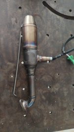
Related question, as I have nothing to compare it to, do you think the placement of my oxygen sensor in the exhaust is correct? I increased the tube diameter so it wouldn't restrict flow, but is it too far downstream? I'm sort of counting on it's values for tuning.

I suppose I could also try a real straight pipe to test if the exhaust I'm using is restrictive or not. I can knock one of those up pretty quick.
 
Last edited:

Rat

Well-known member
Messages
1,750
Reaction score
1,298
Location
SW Virginia
I have taken out the emulsion tube and it has 4 holes on top and 4 on the bottom. I did a web search and found images of an "upgraded emultion tube" with lots of holes, but the regular one seems to have 4 on top and 4 on the bottom.
Forgot to consider that the 'kuni would have a different style E-tube
On the online store I use, they sell 3 versions, 8, 16 and 30 holes for this emulsion tube. Is it worth buying those to try? Not money worth it, is it likely to give results worth trying. They are not expensive. Or is it a better test to drill out the top 2 holes the emulsion tube I have?
"Worth it" is more for you to decide. I'd say the 8h and 16h... try the 8h in it first because you don't want to go too lean.
Related question, as I have nothing to compare it to, do you think the placement of my oxygen sensor in the exhaust is correct? I increased the tube diameter so it wouldn't restrict flow, but is it too far downstream? I'm sort of counting on it's values for tuning.
No idea, I tune by throttle response and plug color. If there's hesitation there's a problem it's just that simple.
I suppose I could also try a real straight pipe to test if the exhaust I'm using is restrictive or not. I can knock one of those up pretty quick.
Maybe don't put a sensor bung in it
 

busted_blocks

Active member
Messages
110
Reaction score
99
Location
Dongguan, China
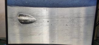
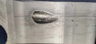
I ran the engine today with the new connecting rod. I might have left a small bur on the through hole, there is a groove now. Overall though it looks much better than the previous one. A little wear around the hole under magnification. inconclusive if it's an improvement of any kind at this kind of rpm. Which makes sense, it was added for effect at very high rpm which I won't try before the engine is broken in.
connecting rod to crank clearance 0.0025". torqued 11ft.lb

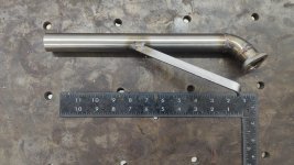
I made a straight pipe today but still need to clean it up after welding. I didn't try it on the engine yet

***[Might all be irrelevant, engine might have other issues. See next post]***

I drilled the top 2 holes (2 of 8) in the emulsion tube slightly larger, up to 0.028". Not sure it made a difference. I made some observations about the carb. I still think it's just very rich and so hard to tune. Hard for me, as I don't understand what I'm seeing and what to do about it. Everything seems too rich. Let me give some observations, and maybe there are clues others can pick up on.

Starting with 32 pilot and 90 main. This is what I ran the engine on during the first break in.
- Idle speed screw is pretty responsive. All the way in gives almost 4000 rpm
- mixture screw is responsive and I was able to find a setting that slowed the rpm if I turned the screw either way.
- instant WOT from idle stall the engine
- Slow increase in throttle, or quick WOT from 3500rpm up is responsive
- Looking at the oxygen sensor, dropping the rpm, say with the idle screw, then engine leans right up and then slowly comes back up to 12:1
- Didn't push engine to higher than 5000rpm, it's on the stand basically unloaded. Spins the wheels but it's in the air

32 pilot 120 main
-Idle screw needs to be all the way in to even get to 2000rpm
- instant WOT from idle stalls the engine

38 pilot 120 main
- hard to get to idle well, even with idle screw all the way in. 1500rpm seems like a struggle.
- mixture screw basically has no effect
- instant WOT will still stall engine
- almost instant WOT has good response
- rpm is very slow to come down after releasing throttle

I tried 32/34/38 pilots with 90/105/120 main jets.
I tried max/min/middle needle positions
I raised the needle, then enlarged the main jets and the throttle response did seem to keep getting better, but the engine was much more rich at idle, even with 32 pilot (with 120 main) and the idle screw needed to be almost all the way in to get it to not stall from low rpm, which to me should be able to get the rpms over 2500 easily. I'm I chasing my tail doing this on the stand and basically unloaded and not driving around?

The engine is running stock timing. I'm planning to advance it 28-20 deg, but I need to measure what it's at now, and I didn't figure it mattered for break in. stock timing should be ok for low rpm.

I put the PE22 carb on that I had running on a similar engine, idles OK, still stalls from instant WOT. I didn't run it much with this, started raining... but it did run OK.

Pulled the spark plug, very black.
 

Attachments

  • straight pipe.jpg
    straight pipe.jpg
    1.2 MB · Views: 4
  • scoop9.jpg
    scoop9.jpg
    1.2 MB · Views: 2
  • scoop8.jpg
    scoop8.jpg
    1.3 MB · Views: 4
  • scoop7.jpg
    scoop7.jpg
    1,013 KB · Views: 4
Last edited:

busted_blocks

Active member
Messages
110
Reaction score
99
Location
Dongguan, China
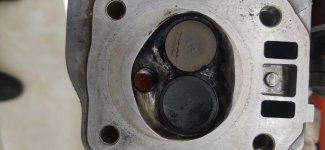
before I go too far down the carb tuning route, there seems to be oil in the cylinder and on the head. Thick black buildup on the inside of the head. To me, this indicates a much larger issue. Since this engine is mostly used parts, I need to look for any mechanical issues.

The good news, the connecting rod seems to be holding up, and I can test at higher rpm. The carb issues must be related to the oil in the cylinder. I use new rings but maybe there is a problem with the block. I'll take everything apart and measure. I guess it always possible I over filled the oil?
 

Attachments

  • head oil.jpg
    head oil.jpg
    1.1 MB · Views: 3
  • piston.jpg
    piston.jpg
    2.9 MB · Views: 3

Rat

Well-known member
Messages
1,750
Reaction score
1,298
Location
SW Virginia
38 pilot 120 main
- hard to get to idle well, even with idle screw all the way in. 1500rpm seems like a struggle.
- mixture screw basically has no effect
- instant WOT will still stall engine
- almost instant WOT has good response
- rpm is very slow to come down after releasing throttle
This is lean behavior not rich

A rich engine will hesitate to ramp up, but will throttle down pretty normally

A lean engine will ramp up stupid quick, but struggle to come back down

Maybe don't build an engine from so many "junk parts"
 

busted_blocks

Active member
Messages
110
Reaction score
99
Location
Dongguan, China
This is lean behavior not rich
Hmm, well I can try bigger.
Maybe don't build an engine from so many "junk parts"
Fair, and the point was to put something together quickly to test the connecting rod. But part of my goal is to learn what is a usable part and what really is too junky. For example the crank is used but it has a solid cam gear. My other new cranks all have sintered cam gears that I don't particularly like. Also in this block there was zero side to side play when assembled so I used the used one. I don't see anything wrong with the block and the head isn't warped, valves seal OK. Might be the gasket, or too much oil. I'll have to test as I don't know which direction the oil is coming in from.

I'm not debating junk parts, but I think they aren't the first ones you think of. The head gaskets look right, but instead of having a line of red sealant around them, they printed a red line on the gasket. So maybe I should be adding an RTV silicone on this type of gasket. I don't think the used head or used block are the issue, but I'm willing to admit it is possible.

I'll post something when I have more news on this connecting rod.
 
Last edited:

Rat

Well-known member
Messages
1,750
Reaction score
1,298
Location
SW Virginia
Hmm, well I can try bigger.

Fair, and the point was to put something together quickly to test the connecting rod. But part of my goal is to learn what is a usable part and what really is too junky. For example the crank is used but it has a solid cam gear. My other new cranks all have sintered cam gears that I don't particularly like. Also in this block there was zero side to side play when assembled so I used the used one. I don't see anything wrong with the block and the head isn't warped, valves seal OK. Might be the gasket, or too much oil. I'll have to test as I don't know which direction the oil is coming in from.

I'll post something when I have more news on this connecting rod.
There nothing wrong with reusing old parts, hell I resurrected 2 engines that were full of more water than oil and had been that way for God only knows how long. Cleaned them up replaced only the carb on both, both ran on the bench.

One needs seals and a head gasket, one needed rings but I scaped some parts instead, and I won't use either one at this point
 

busted_blocks

Active member
Messages
110
Reaction score
99
Location
Dongguan, China
I've got an update and I'm going to split it up. I'll keep the connecting rod related stuff here, and I'm going to update my thread on "blowing gas out the carb" because that's what it's doing and I think it's best to keep things together so they might be easier for someone else to find in the future, assuming i get it solved :ROFLMAO:

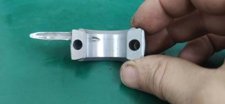
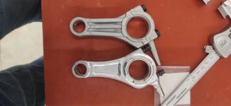
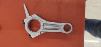
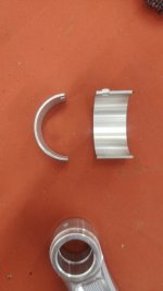
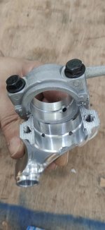
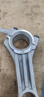
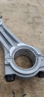
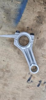
I found a new type of stock connecting rod. It's for a diesel engine but in the same 170F/168F family. It's got a 32mm hole for the crank and 18mm for the piston pin. The center to center distance is the same as stock GX200 rod. The shank is thickened with a rib down the middle and the casting is almost as good quality as the Honda connecting rod I have. Under magnification you can see little pits in all the castings, but less in the Honda. On a side note, this goes to show why billet parts will always be stronger, even if the shape is identical, but I digress. The material of this rod is thicker than the normal GX200 rod around the 32mm hole (over 8mm at the smallest point) and comparable to the Arc CNC rod. There is a recessed bit where the top and bottom of the rod are bolted together. maybe to allow in oil, anyway is 33mm exactly. I need to open up the hole to 33mm and then I can fit the clam shell bearing in. The current dimensions show I can 100% make a 33mm hole and not hit the bolt threads. The clam shells are a standard part for a different 170F engine, so they are also very cost effective.

I'm planning to make the oil paths similar to the Arc Rod. I have a cutter to make the inside 2.5mm groove and new 2.5mm drill for a hole by the oil dipper. I'm not going to do any welding on this one as the optimal finished rod is easy to produce and the welding extra material is a bit fiddly. Might take me a few days to setup but I should have something to show soon.

On the other connecting rod with the welded scoop, the engine is running well but has some carb issues still. It's running around the track and has good torque. The previous oil in the cylinder was due to something wrong with the head I was using. Maybe it was coming in through worn valve guides? Not sure but the intake valve was damaged and there was all kinds of stuff "welded" on the intake tube. Replaced that and there is no more oil in the cylinder. I did measure the piston and bore, both are in spec.
 

Attachments

  • 32mm rod3.jpg
    32mm rod3.jpg
    817.3 KB · Views: 6
  • 32mm rod2.jpg
    32mm rod2.jpg
    1.1 MB · Views: 6
  • 32mm rod.jpg
    32mm rod.jpg
    1,000.4 KB · Views: 6
  • clam shell.jpg
    clam shell.jpg
    888.9 KB · Views: 5

Rat

Well-known member
Messages
1,750
Reaction score
1,298
Location
SW Virginia
I've got an update and I'm going to split it up. I'll keep the connecting rod related stuff here, and I'm going to update my thread on "blowing gas out the carb" because that's what it's doing and I think it's best to keep things together so they might be easier for someone else to find in the future, assuming i get it solved :ROFLMAO:

I found a new type of stock connecting rod. It's for a diesel engine but in the same 170F/168F family. It's got a 32mm hole for the crank and 18mm for the piston pin. The center to center distance is the same as stock GX200 rod. The shank is thickened with a rib down the middle and the casting is almost as good quality as the Honda connecting rod I have. Under magnification you can see little pits in all the castings, but less in the Honda. On a side note, this goes to show why billet parts will always be stronger, even if the shape is identical, but I digress. The material of this rod is thicker than the normal GX200 rod around the 32mm hole (over 8mm at the smallest point) and comparable to the Arc CNC rod. There is a recessed bit where the top and bottom of the rod are bolted together. maybe to allow in oil, anyway is 33mm exactly. I need to open up the hole to 33mm and then I can fit the clam shell bearing in. The current dimensions show I can 100% make a 33mm hole and not hit the bolt threads. The clam shells are a standard part for a different 170F engine, so they are also very cost effective.

I'm planning to make the oil paths similar to the Arc Rod. I have a cutter to make the inside 2.5mm groove and new 2.5mm drill for a hole by the oil dipper. I'm not going to do any welding on this one as the optimal finished rod is easy to produce and the welding extra material is a bit fiddly. Might take me a few days to setup but I should have something to show soon.

On the other connecting rod with the welded scoop, the engine is running well but has some carb issues still. It's running around the track and has good torque. The previous oil in the cylinder was due to something wrong with the head I was using. Maybe it was coming in through worn valve guides? Not sure but the intake valve was damaged and there was all kinds of stuff "welded" on the intake tube. Replaced that and there is no more oil in the cylinder. I did measure the piston and bore, both are in spec.
Being a Diesel rod it should handle high compression exceptionally well
 

busted_blocks

Active member
Messages
110
Reaction score
99
Location
Dongguan, China
There has been a bit since I gave an update. Chinese New Year is over so things are getting back to normal.

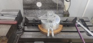
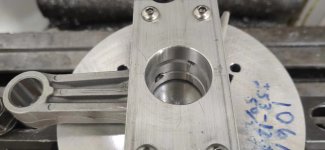
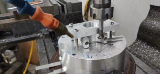
The first problem to overcome with the diesel connecting rod is that there are no external reference surfaces. I assume they just clamp it at the factory and machine the wrist pin and crank shaft hole in one go. Since there is no second setup, no reference surfaces are needed. So I have to indicate on the bore and align it that way. Easier say than done. Plus to clamp the rod without deforming it, it's helpful to have a flat surface top/bottom on the rod.

I modified my fixture for holding cylinder heads with a top clamping pate with a hole in it. Then by some good luck I had an unused lathe mounting plate that matched the hole spacing on my fixture. By bolting to the 2 together, I ended up with a way to independently shim the fixture in X/Y axes. I did try shimming both at once but it was a PITA and didn't work. By indicating the large bore and shimming, I was able to get the rod setup. In fact the check to see if it's good enough is indicating on the wrist pin end as that's the surface that will remain unchanged.

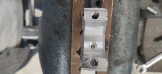
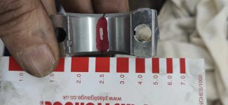
My first attempt wasn't perfect, but the second seems to be decent. I put in an oil groove (depth limited by bolt holes) and the alignment grouves for the bushing. I measured the clearance with plastigauge and is pretty close to .0025 - .003 clearance. I'll add a hole in the bushings to allow the oil in and I think it will be good.

One of issues I see with the cast rods in general is that the surface is just not great at a microscopic level. Pits and inclusions and what not. So one of the biggest advantages of the shell bearing is the specially formulated bearing surface.

It might be a bit before I get to test it though as I'm still working on carb tuning and I have to repair the front end from little crash.
 

Attachments

  • conrod setup.jpg
    conrod setup.jpg
    1.2 MB · Views: 4
  • conrod big end.jpg
    conrod big end.jpg
    873.4 KB · Views: 5
  • conrad compare.jpg
    conrad compare.jpg
    2 MB · Views: 5
  • conrod shell tab.jpg
    conrod shell tab.jpg
    1 MB · Views: 5
  • conrod finished.jpg
    conrod finished.jpg
    946.7 KB · Views: 5
  • conrod plastigauge.jpg
    conrod plastigauge.jpg
    857 KB · Views: 5
  • conrod done3.jpg
    conrod done3.jpg
    2.1 MB · Views: 6
  • conrod done2.jpg
    conrod done2.jpg
    2.1 MB · Views: 4
  • conrod done1.jpg
    conrod done1.jpg
    2.6 MB · Views: 4

Rat

Well-known member
Messages
1,750
Reaction score
1,298
Location
SW Virginia
It’s been a while, since I watched this.
200cc utility engine with pressurized lube / oil pump.

It's not that complicated to do, my 208 is running a 12v external pump, remote filter, a check valve sandwich block, and an oil cooler.

If I wanted to make it a little more a true to trait pressurized system, I'd just relocate the return port to the topside where the governor linkage plug is
 
Top