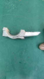
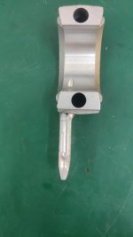
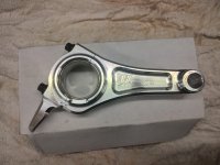
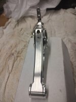
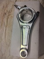
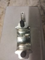
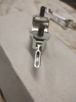
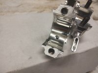
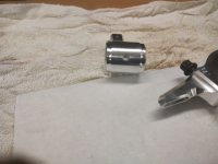
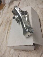
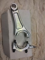
Designing a connecting rod, I'd love some insights on how stock rods fail etc.

Thepartsguy

Well-known member
Messages
1,559
Reaction score
1,445
Is there any benefit to a groove in the crank rather than a groove in the conrod journal?
The insert or rod is aluminum and seems like grooves would become a ware point. Think it wares the journal down till it’s even deep with the grooves you cut in it? The crank is steel
 

busted_blocks

Active member
Messages
110
Reaction score
99
Location
Dongguan, China
The insert or rod is aluminum and seems like grooves would become a ware point. Think it wares the journal down till it’s even deep with the grooves you cut in it? The crank is steel
Any groove that's straight provides an area of no contact between the 2 parts. So whether the crank doesn't touch the rod or it's the rod journal not touching the crank, I feel you have equal total surface area and thus the same wear. I could be thinking about it wrong but anway...
So what about a spiral groove in the crank? Then you have contact, though slightly intermittent on the entire conrod surface. I guess you might what it to be a figure 8 shape so it recirculates teh oil, not pumps it like a screw off one end..

As previously mentioned, I'm probably over thinking this way too much. So many things to try, and ideally all tried under the same conditions so they can be evaluated after a set amount of time.
 

Rat

Well-known member
Messages
1,750
Reaction score
1,298
Location
SW Virginia
Is there any benefit to a groove in the crank rather than a groove in the conrod journal?
The crankshaft rotates, the conrod reciprocates but is for this purpose is a stationary object, the spiral requires rotation to function.
 
Last edited:

Rat

Well-known member
Messages
1,750
Reaction score
1,298
Location
SW Virginia
I guess you might what it to be a figure 8 shape so it recirculates teh oil, not pumps it like a screw off one end..
No, you are over thinking way too far and its becoming a bit convoluted.
A figure 8 would not recirculate anything it would just defeat the entire purpose.

You must not be familiar with the Plane Screw... its one of the oldest, if not THE oldest mechanical pump design on the planet.

It's also known as an auger in its modern use.

How does a meat grinder work? An auger, aka screw, aka worm gear aka spiral twisted flat blade.

There are easily a million examples of why a screw or in the specific instance a spiral groove would be the ideal primitive pump for the task.

A straight line groove creates a single point of consistent uniform non contact for the entire length of the groove, which will become a stresser as well as upset the crank balance ever so slightly.

A spiral will not upset balance provided the stop does not exceed the start (precisely 360° spaned across the entire width)

Too much spiral and it will not function as intended. Not enough and you have a bigger problem, which is why in old engines that use this method of drawing oil into a bronze sleeve bushing or even a babbitt, the pitch was determined by the length

A spiral would provide a non contact point only the width of the groove, but still fully in contact with the rod end unlike a straight line where there is just a uniform gap that also does nothing to leverage the crank rotation.
 
Last edited:

busted_blocks

Active member
Messages
110
Reaction score
99
Location
Dongguan, China
No, you are over thinking way too far and its becoming a bit convoluted.
A figure 8 would not recirculate anything it would just defeat the entire purpose.

You must not be familiar with the Plane Screw... its one of the oldest, if not THE oldest mechanical pump design on the planet.

It's also known as an auger in its modern use.

How does a meat grinder work? An auger, aka screw, aka worm gear aka spiral twisted flat blade.

There are easily a million examples of why a screw or in the specific instance a spiral groove would be the ideal primitive pump for the task.

A straight line groove creates a single point of consistent uniform non contact for the entire length of the groove, which will become a stresser as well as upset the crank balance ever so slightly.

A spiral will not upset balance provided the stop does not exceed the start (precisely 360° spaned across the entire width)

Too much spiral and it will not function as intended. Not enough and you have a bigger problem, which is why in old engines that use this method of drawing oil into a bronze sleeve bushing or even a babbitt, the pitch was determined by the length

A spiral would provide a non contact point only the width of the groove, but still fully in contact with the rod end unlike a straight line where there is just a uniform gap that also does nothing to leverage the crank rotation.
Fair enough. A spiral on the crank could be helpful for oiling. A hole is relatively easy to do but a spiral is a bit more tricky and I'm not exactly sure how to accomplish that with a decent degree of accuracy.

It's sometimes difficult when one doesn't have the background in engines to know what to do to make them work, hence the convoluted thinking. That being said, I do try and do thing methodically, so I'll try to avoid doing anything crazy.

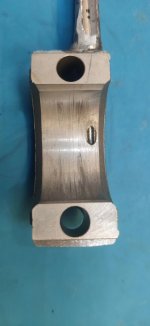
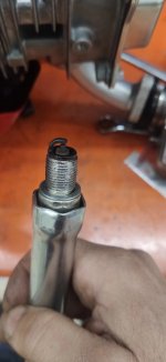
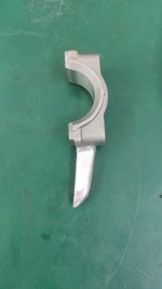
I built a bottom end with the connecting rod with the scoop. Did not use all new parts. I used a new piston+rings and bearings, but the crank, case, cam were all used. The crank looked OK, no obvious wear. I ran the engine on the stand at rpms from 2500-4000 for an hour. I was not able to lean out the engine. I decidedly do not like the PWK24's I bought. Part of that could certainly user error, but I have the smallest pilot jet, needle in the lowest position, pilot (air) screw all the way out, and it's still rich. That is a separate issue and best I not get off topic.

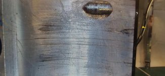
The rod does not look great after an hour of running. I would have expected it to look normal, with the scoop having had zero affect during break-in. I'm not going to blame it on the scoop, but I wouldn't feel comfortable putting this connecting rod back in the engine. I'm not sure if it's not enough clearance. I'll check with plastigauge. I was in a rush to get out to test today and didn't measure the clearance before installing it. I tightened the connecting rod to 11ft.lb.
 

Attachments

  • con rod.jpg
    con rod.jpg
    2.4 MB · Views: 7
  • rod closeup2.jpg
    rod closeup2.jpg
    2 MB · Views: 6
  • rod closeup1.jpg
    rod closeup1.jpg
    1.3 MB · Views: 6
  • spark plug.jpg
    spark plug.jpg
    1.7 MB · Views: 7

busted_blocks

Active member
Messages
110
Reaction score
99
Location
Dongguan, China
The damage looks more like it is from contamination than lack of oil.
I don't suspect lack of oil either. Contamination is possible, might be the oil funnel at the track. If so it's almost comically absurd. Rod to crank clearance measured at .002" with plastigauge. It's on the small side.
 

Darren

Active member
Messages
163
Reaction score
238
Location
Essex, England
First of all, nicely done. This is the sort of stuff I live for.
I totally agree with Denny, I think your rod may have suffered a bit with oil contamination.
The rod is not destroyed, so you may be able to check your clearance with some Plastigauge.
I haven't installed my ARC rod, so can take some detailed pictures of the oil scoop and shells to help with oil pathways etc...
The pictures won't be uploaded for another 7 hrs, sorry work commitments.
 

busted_blocks

Active member
Messages
110
Reaction score
99
Location
Dongguan, China
The damage looks more like it is from contamination than lack of oil.
First of all, nicely done. This is the sort of stuff I live for.
I totally agree with Denny, I think your rod may have suffered a bit with oil contamination.
The rod is not destroyed, so you may be able to check your clearance with some Plastigauge.
I haven't installed my ARC rod, so can take some detailed pictures of the oil scoop and shells to help with oil pathways etc...
The pictures won't be uploaded for another 7 hrs, sorry work commitments.
I looked again at the close up image of the oil hole coming in from the scoop. If you look, there is a pattern on only one side of the hole, sort of pointing towards the inside of the con rod. Let's assume contaminated oil, with say pumice stone dust, the rotation of crank would be pulling oil in that direction. Seems to show a direction of flow and that there is oil coming from there and moving towards the center of the conrod. The contaminated oil leaving a ground patch there.

Contaminated oil is an easy fix. Buy a new funnel.

@Denny A picture of the inside of the conrod would be great. I'd love to see if it has that strange hole to no where.
 

busted_blocks

Active member
Messages
110
Reaction score
99
Location
Dongguan, China
Try number 2...

I'll clean the engine thoroughly and try again tomorrow.

I'm not sure it was worth the effort to drill the hole on angled towards the center. The geometry of the scoop limits the angle as does the bolt hole and it complicates the machine setup as you have to angle the part in 2 directions.
 

Attachments

  • scoop5.jpg
    scoop5.jpg
    837.6 KB · Views: 4
  • scoop4.jpg
    scoop4.jpg
    876.7 KB · Views: 4
  • scoop3.jpg
    scoop3.jpg
    853.1 KB · Views: 4
  • scoop2.jpg
    scoop2.jpg
    827.7 KB · Views: 5
  • scoop1.jpg
    scoop1.jpg
    861.1 KB · Views: 5
  • scoop6.jpg
    scoop6.jpg
    2.2 MB · Views: 5

Rat

Well-known member
Messages
1,750
Reaction score
1,298
Location
SW Virginia
I decidedly do not like the PWK24's I bought. Part of that could certainly user error, but I have the smallest pilot jet, needle in the lowest position, pilot (air) screw all the way out, and it's still rich.
Seeing as anything below PWK28 is NOT a genuine PWK (Keihin) it could be a cheap bad copy, or it could be that you don't have a background in engines.

There are cheap problematic copies, and there are those that just need a little help to be what they pretend to be but since you are trying to use a motorcycle carburetor in a nonstandard application... of course it's not going to work worth a damn if you don't put in the work.

The simplest thing you can do is double check the float hight and check the enrichment plunger for debris and being loose. The enrichment circuit is an easy corrected common issue with those carbs

I run a PWK24 on my 208 and I don't have those issues but that engine is pretty far from stock too.
Emulsion tube drilled
2t Power jet deleted
Lots of hours dialing it in
 

Darren

Active member
Messages
163
Reaction score
238
Location
Essex, England
ARC ROD DETAILS
 

Attachments

  • pic1.jpg
    pic1.jpg
    331.6 KB · Views: 10
  • pic2.jpg
    pic2.jpg
    261.3 KB · Views: 10
  • pic3.jpg
    pic3.jpg
    326 KB · Views: 10
  • pic4.jpg
    pic4.jpg
    221.6 KB · Views: 10
  • pic5.jpg
    pic5.jpg
    201.7 KB · Views: 10
  • pic6.jpg
    pic6.jpg
    246.7 KB · Views: 10
  • pic7.jpg
    pic7.jpg
    280.8 KB · Views: 9
  • pic9.jpg
    pic9.jpg
    232.1 KB · Views: 10
  • pic8.jpg
    pic8.jpg
    278.7 KB · Views: 9
  • pic10.jpg
    pic10.jpg
    337.8 KB · Views: 9

Thepartsguy

Well-known member
Messages
1,559
Reaction score
1,445
Looks like the dipped is a lot more of a spoon than actually having a weep hole into the crank
That would be the inlet drilled for the forced oil. arc enduros have the dipper but no hole drilled. 4cycleforums said that the enduro rods with the non forced oil hole in the slinger on the enduros did slightly better.
 
  • Like
Reactions: Rat

busted_blocks

Active member
Messages
110
Reaction score
99
Location
Dongguan, China
Looks like the dipped is a lot more of a spoon than actually having a weep hole into the crank
@Darren thanks for the pics, I'm sure the copy I have is exact.

I can't see hole I'm unsure of, you can see it in a previous post, but since everything else is exactly the same, I'm pretty confident that hole is in the original as well.

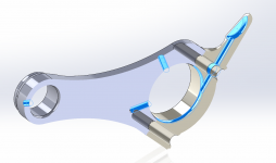
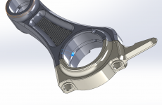
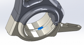
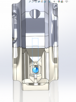
@RLS_Underground It's a hole very similar to what I made. It's hard to see in the pictures because the bushing is installed. I'll attach some more pictures of the 3D model. In the picture in my previous post, you can see the path from the spoon to the journal. Note the cutout in the bolt clearance hole to allow the oil to get around the reduce shank bolt and into the journal. So many machining setups in that rod. I tried to highlight the oil paths in blue on a cut-away. My model does not have the bushing included, so the oil paths are easier to see.
 

Attachments

  • arc4.png
    arc4.png
    273.4 KB · Views: 2
  • arc3.png
    arc3.png
    538.7 KB · Views: 2
  • arc2.png
    arc2.png
    244.2 KB · Views: 1
  • arc1.png
    arc1.png
    213.7 KB · Views: 1
Top