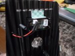
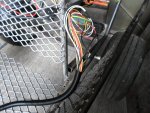
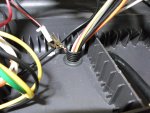
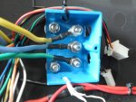
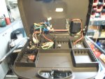
OK, so that covers the "big stuff" (the main power wires)
The (2) battery cables carrying the power/amperage from the battery pack to the speed controller
…& then, the (3) motor cables that deliver that power/amperage (upon your command) from the controller to the motor

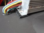
Now for the "small power" or signal/sensor/control wires
...these wires are for sending/receiving information & to activate control functions
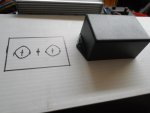
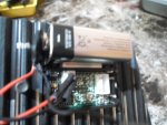
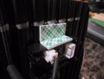
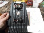
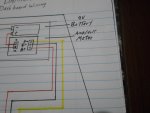
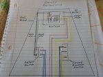
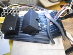
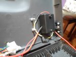
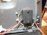
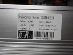
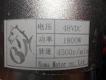
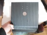
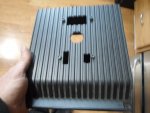
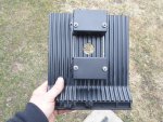
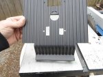
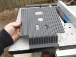
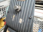
Here is the "Wires Interface Definition", I got from the seller, for this "Brainpower" 48V 1,800W motor controller
...it's not very accurate & even leaves some really important stuff out  Battery :Thick Black (Power Negative) /Thick Red (Power Positive)
Motor :Thick Yellow (Motor Negative) /Thick Blue (Motor Positive)
Ignition Switch :Thin Red(VCC)/Thin Blue
Indicator : Thin red (Indicator power output) /thin black (indicator negative)
Brake :thin yellow (Brake signal)/thin black(Negative Power)
Speed governor :Thin blue(Speed handlebar Signal input) /Thin black (Negtive Power) /thin red(5V Positive Power)
Charge Port : Thin red (charge input power Positive) /thin black (Power negative)
Brake Light: Thin red (power Positive) /thin black (Power negative)
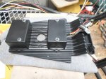
First off, this "Wire Definition" only shows (2) motor wires (thick yellow & thick blue)
...what about that thick green fella? it's not important?
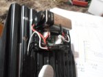
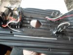
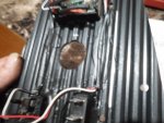
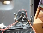
Second, it only shows/defines (6) plugs
...when there are actually (10) plugs/connections for this speed controller
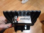
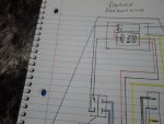
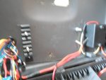
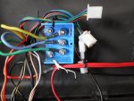
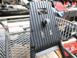
So, here is the wire definitions, I came up with
 Big Power Wires
Battery
Big Power Wires
Battery: thick Red, thick black
...these are where the Positive (+) & Negative (-) battery cables connect
Motor: thick Yellow, thick Blue, thick Green
...these wires send the "amperage" current from the speed controller to the motor
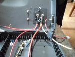
Small Signal/Control wires
#1 Hall: thin Red, Black, Yellow, Green & Blue
...these are the signal wires that relay info between the motor & the speed controller
#2 Ignition Switch: thin Red, thin Black
...actually labeled "Power Lock", this is where the key (on/off) switch connects
#3 Throttle: thin Red, thin black, thin green
...this is where the throttle wires connect
...their diagram labels this one as "Speed governor"
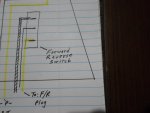
#4 Forward & Reverse: thin Yellow, thin Black, thin Gray
...their diagram completely left this one out
…& without a switch connected to this plug, this system will NOT work
(because the controller doesn't know if you want to go forward or backwards)
#5 3-Speed: thin Blue, thin Black, thin Green
...connect an On/Off/On switch here to be able to select low, med or high speed
(if a switch is not connected to this plug the system WILL still operate
...but, it would only operate at medium speed, the "default Mode"
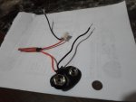
#6 Charge Port: (Red plug) Thin red, thin black
I'm not gonna charge thru the controller
...instead, I connected the charge port (basically) directly to the battery pack
#7 Brake : thin White, thin Orange
...this is where the Brake lever switch wires attach
#8 Brake Light: thin White, thin black
...these wires send current (when the brake lever is activated) to activate "power" the brake lights
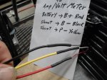
#9 Indicator : thin Orange, thin black
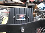
...this one seems to be for connecting a Voltage meter
#10 Hour Meter (Black plug) thin Red, Blue. Green, Black
...still researchin' on this one 
 SAM_4424.JPG1.3 MB · Views: 2
 SAM_4425.JPG1.2 MB · Views: 1
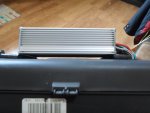 SAM_4427.JPG1.3 MB · Views: 1


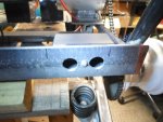
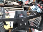
 The back side of the spring striker bar (2" x 2" angle steel) is right above & in front of the rear bumper.