Doc Sprocket
*********
LOL
Trust me- the motor's nothing new... I'll have to shoot some closeups of it. The spindle's just being crotchety. I THINK I know how to get it off, once it chooses to co-operate. I believe it's a tapered chuck, and there's a threaded collar between the chuck and spindle. I THINK I need to hold the chuck/spindle still, and turn that collar up until it forces the chuck out. I'll go shoot a closeup shortly.
Since I don't have anything In print, I THINK low speed is 450-500 RPM based on pulley sizes, and 1725RPM motor. I would LOVE for it to go much slower, considering the chuck capacity is 5/8". Makes me wonder if I can lay hands on a lower-speed motor, or maybe do my own compound reduction with an extra shaft and pulleys...
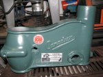
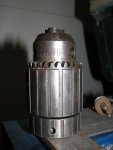
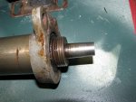
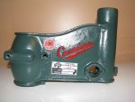
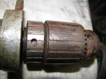
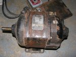
EDIT- Some pics. the collar above the chuck is internally threaded. If you look closely you can see the threads it rides on. The motor- Definitely old! Cast iron housing, and an oil port at each bearing. The ports are threaded, with a screwdriver slot. I just did a bit of research, and found the following blurb: "Leland Electric had a Canadian Subsidiary, Leland Electric Canada Ltd., which was active until at least 1957." Original motor, anybody?
Trust me- the motor's nothing new... I'll have to shoot some closeups of it. The spindle's just being crotchety. I THINK I know how to get it off, once it chooses to co-operate. I believe it's a tapered chuck, and there's a threaded collar between the chuck and spindle. I THINK I need to hold the chuck/spindle still, and turn that collar up until it forces the chuck out. I'll go shoot a closeup shortly.
Since I don't have anything In print, I THINK low speed is 450-500 RPM based on pulley sizes, and 1725RPM motor. I would LOVE for it to go much slower, considering the chuck capacity is 5/8". Makes me wonder if I can lay hands on a lower-speed motor, or maybe do my own compound reduction with an extra shaft and pulleys...
EDIT- Some pics. the collar above the chuck is internally threaded. If you look closely you can see the threads it rides on. The motor- Definitely old! Cast iron housing, and an oil port at each bearing. The ports are threaded, with a screwdriver slot. I just did a bit of research, and found the following blurb: "Leland Electric had a Canadian Subsidiary, Leland Electric Canada Ltd., which was active until at least 1957." Original motor, anybody?
Attachments
-
 IMG_0844.JPG171.9 KB · Views: 8
 -
 IMG_0846.JPG226.5 KB · Views: 10


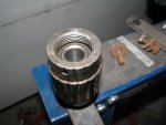
 OUCH!! Here's where I get hoisted by my own petard; I've seen chuck mount's like that, but I've never had to tear one down. First thoughts on it; if this was powered from new with a single Phase 120 V motor, then it threads on (as viewed from the front) from left to right; that's where the past history of the unit becomes very critical, as well as having it in my hand; the whole knowing when to back off before you destroy some thing is very critical.
 make the chuck very difficult , if not impossible to use.