American Ethos (2025) Electrathon America Racer

Functional Artist

Well-known member
Messages
5,345
Reaction score
2,834
Location
Toledo, Ohio
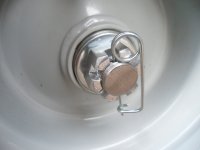
Um, I don’t feel worthy enough to point out your mistakes. But I feel I must for your safety. Unbolt that band and rotate to until the open side is at the top please? Then hook your brake rod on to the rear most loop. This way the brake will self energize when applied and help you stop. And release properly when not applied.
Hey Denny,

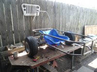
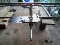
In this pic, the front of the racer (& direction of travel) is toward the left
...& the motor(s) will be mounted, behind the wheels :thumbsup:
SAM_4772 (1).JPG
So, this wheel, will rotate counter-clockwise
...& the brake cable (not rod) will "feed thru" the upper slot in the brake band
...& then, will attach to the lower hole/slot via a "fitting" (forgot what they are called??)

The brake cable housing, will terminate at
...& "seat against" the upper brake band, slot

So, when the brake is applied
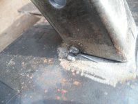
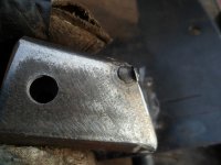
1.) the "force" of the brake band, will push the mounting bolt (& mount) upwards into the bottom of the Nacelle "plate"
...& this design, should "hold" it there good-n-firm

2.) by having the brake band "actuating & gripping" in the same direction of rotation as the brake drum (& wheel)
...the rotation of the brake drum actually helps the brake band "grip better"

* I think this the "self-energize when applied" you are referring to :cheers2:

"Fighting" against the direction of rotation
...would be detrimental to "good braking action" ;)

3.) the natural "spring action" of the brake band helps it to "release"

No, pics of this "cable set-up"...yet
...as, I haven't got that far...yet :cornut:
 
Last edited:
Functional Artist

Well-known member
Messages
5,345
Reaction score
2,834
Location
Toledo, Ohio
After weldin' the axle mount(s) in place
...I re-assembled...everything...again
...& double checked...everything...again :thumbsup:

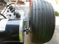
Motor to wheel chain alignment still "lookin' good"...check :wai:
SAM_4787 (2).JPG
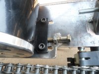
Motor/chain tensioner operating properly...check :wai:
SAM_4788 (2).JPG
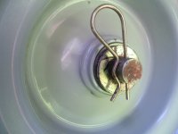
Wheel to axle retaining pin(s)...check :wai:
SAM_4799.JPG
Then, Ducky meows...what about "nut(s)"
...& another meow...don't ya need a Castle style retaining nut?? :unsure:
SAM_4800.JPG
Well, your just a cat
...so, how would you know??? :p
But, just to be sure...I'll double check, the Electrathon America official rulebook :popcorn:
&
Here is what I found, under the Vehicle Design Rules section: ;)

9 BRAKES and AXLES
1. At least two wheels must have brakes.
2. Brakes must be fitted to two wheels of the same axle. Either both front wheels or both rear wheels depending on vehicle construction.
3. The two brakes must have separate actuation cables. If both brakes are to be actuated by a single hand or foot lever, then both cables should be attached to the lever.
4. Regenerative braking is permitted in addition to conventional brakes.
5. The vehicle must not roll if pushed while brakes are applied. The vehicle must also be able to demonstrate a straight stop from a speed of 25MPH in less than 40 feet.
6. Axles supported at both ends must have a diameter of at least3/8"(10mm).
7. Axles supported only on one end must have a diameter at least½"(12mm)
8. Safety wire or cotter pins must be used to secure cantilevered wheel axle nuts. Nylon lock nuts and double nuts alone are not acceptable.

10 WHEELS and TIRES
1. Tires must be a pneumatic (inflatable) type.
2. Wheels and tires of any diameter or width may be used.
3. The minimum ground clearance is to be judged by the cars ability to rollover a 2x2 that is milled to be1½”x1½”. This is to prevent the vehicle from sliding on the ground in the event of failure of any or all of the tires.
4. While in driving position the driver's body must not be able to come in contact with tires, wheels or spokes.
(page 8.)

Then, under Vehicle Design Tips, I found:
AXLES
One important note: DO NOT USE BICYCLE OR MOPED AXLES UNLESS SUPPORTED AT BOTH ENDS. If your axles are cantilevered (attached on one side only like a wheelchair) you MUST replace the stock axle with a 1/2" or12mm diameter bolt. Axle diameters less than 12mm are illegal. A bicycle or moped axle WILL break. It is easy to pull out the stock axle and replace it with a larger one. You must replace the wheel bearings with cartridge bearing assemblies. These can be found at bearing supply stores. Use an axle bolt and nut that accepts a cotter pin so your wheel doesn't come off. This is a rule requirement.
(page 23.)

So...yup your right...Ducky
...it looks like we need wheel/axle nuts & safety wire or cotter pins
...to be compliant with the EA rules :cornut:
 

Functional Artist

Well-known member
Messages
5,345
Reaction score
2,834
Location
Toledo, Ohio
So, I got some 5/8"-18 fine threaded Castle nuts
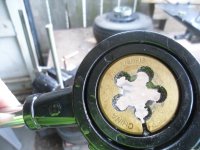
...& then, got out the "big" Tap & Die set

This looks like the fella, we be a needin' :p
SAM_4804 (1).JPG
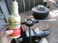
Used some of this here, cuttin' oil
...& cut us some threads, onto the end of the axle/spindle :thumbsup:

* Notice I'ma usin' my "new/old" vise? :cheers2:
SAM_4805.JPG
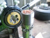
Looks kinda like this...when done
SAM_4806.JPG
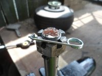
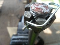
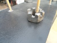
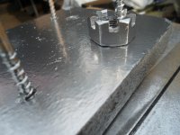
Looks kinda like this, with a Castle Nut & Safety Pin (as per the rule book) ;)
SAM_4807 (1).JPG
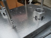
How's about another view? :2guns:
SAM_4808 (2).JPG
 

Functional Artist

Well-known member
Messages
5,345
Reaction score
2,834
Location
Toledo, Ohio
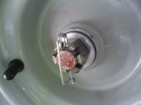
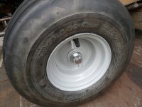
Here is how the Castle Nut & Safety Pin looks "in place" on the wheel :thumbsup:
SAM_4810 (1).JPG
* Notice the Castle nuts are just plain steel
...no Zinc plating
...no Black Oxide
...not nuthin' :ack2:

So, I worked on cleaning 'em up
...but, wiping down a nut, isn't the easiest thing to do
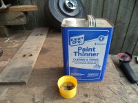
...so, I put 'em in a small container
...poured in a ~1/4 cup of paint thinner
SAM_4811 (1).JPG
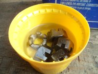
Then, "sloshed" (technical term) 'em around a bit
...gave the outside "faces" of each one a bit of "rubbing"
...& "sloshed" em' around a bit more
SAM_4812 (1).JPG
Set 'em out, on a piece of paper towel, to dry a bit
...then, put 'em on a "mini-pegboard" painting "prop"
SAM_4813 (1).JPG
Before
SAM_4814 (2).JPG
After (a quick spray, with some Rustoleum Chrome spray paint)
SAM_4815 (1).JPG
Flipped em' over (ta do the other side)
SAM_4816 (1).JPG
Here is how the Castle Nut & Safety Pin looks "in place" on the wheel (after paintin') ;)
SAM_4820 (1).JPG
Close up :sifone:
SAM_4819 (2).JPG
 

Functional Artist

Well-known member
Messages
5,345
Reaction score
2,834
Location
Toledo, Ohio
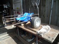
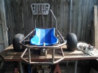
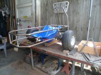
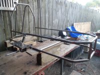
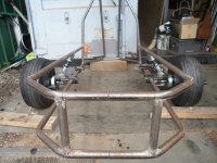
We have a "roller" :wai:
SAM_4821 (1).JPG
But, this "milestone" has revealed an "issue" :ack2:
These coil-over shocks seem to be, TOO weak...for this application :furious2:

It looked pretty good just sitting there :thumbsup:
SAM_4830 (1).JPG
But,
When I sat on it
...it "sank" a couple of inches :mad2:
&
Even when I got up/off of it
...it couldn't/didn't "totally" raise back up :(
SAM_4826 (1).JPG
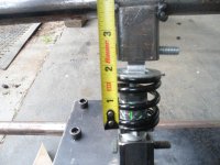
This pic shows the coil-over shock (before sitting on the chassis) in its "unloaded" state (~2")
SAM_4823 (2).JPGIt "sank" way more (~2"- 3")
...& then, only rebound...this much (~1 5/8") :huh:
...after, I got off of it
SAM_4824 (1).JPG
 

Functional Artist

Well-known member
Messages
5,345
Reaction score
2,834
Location
Toledo, Ohio
Re-calculating...re-calculating... :huh:

Well...let's make sure everything else, is workin' together...so far :thumbsup:
SAM_4833.JPG
Hello...Ducky :)
Hmmm, the seat back seems ta be, a bit too high
SAM_4832 (1).JPG
Oh...OK...the "prop" block under the seat is ~4" tall
...& I wasa usin' a couple of 2x4"s (~3 1/2" tall) earlier

Yup, that's better ;)
SAM_4849 (1).JPG
Not a HUGE difference
...but, enough to "throw" my calculations "off" :furious2:

* Also, "robbed" (temporarily borrowed) the coil-over shocks off of my Land Speeder kart
...just for "prop" purposes :cheers2:
SAM_4848 (1).JPG
 

Functional Artist

Well-known member
Messages
5,345
Reaction score
2,834
Location
Toledo, Ohio
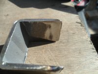
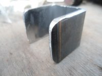
Quick DIY tip
...for makin' "perfect" U-Brackets :2guns:

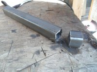
Just cut the side, out of a piece of square tube with the ID. (inside diameter) you need
SAM_4834.JPG
Like for these little coil-over shocks
...they require a 1" ID. U-Bracket
* A 1 1/4" OD. square tube with 1/8" walls has a 1" ID. (1 1/4" - 1/8" - 1/8" = 1') :sifone:

So, I measured
...& marked the material, at 1" (all of the way around)
SAM_4835 (1).JPG
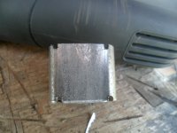
Then cut 'er off (usin' a regular 'ol HF grinder with a metal cut-off wheel attached) ;)
SAM_4836 (1).JPG
Next, I made some "notches" ta help identify, where the "walls" are, for cuttin
SAM_4837 (2).JPG
Then, clamped 'er down
...& used the "notches" as "guides"
...ta cut 'er out
SAM_4839.JPG
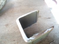
Just gotta "clean off" this little "lip"
SAM_4842 (1).JPG
Kinda like this
SAM_4844 (1).JPG
Then, a little bit of overall clean up
SAM_4847 (1).JPG
This "trick" will help ya to produce nice-n-square U-Brackets...everytime

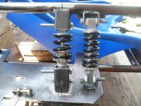
Below is how they look
...on a shock :thumbsup:

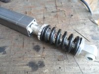
FYI: coil-over shock on the left is ~4" from, bolt hole to bolt hole
...& the one on the right is ~5" from, bolt hole to bolt hole
Although neither of these coil-over shocks have any "specs" on the shock (or spring) itself (cheap Chinese shet) :furious2:
...but, from tryin' some manual actuation
...the one with more coils "is" much more difficult to "actuate"
...so, gonna try 'em next :cornut:
SAM_4851.JPG
 

Functional Artist

Well-known member
Messages
5,345
Reaction score
2,834
Location
Toledo, Ohio
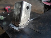
Tac welds are great for testing purposes
...'cause they "hold" (2) pieses (of steel) together pretty good(ly)
...& "if" ya don't like something
...you can remove the piece quite easily
...with just a quick "zip"
SAM_4852 (1).JPG
Clos(er) up
SAM_4853 (2).JPG
Other side
SAM_4854 (2).JPG
Then, just pop 'er off ;)
SAM_4856 (2).JPG
 

Functional Artist

Well-known member
Messages
5,345
Reaction score
2,834
Location
Toledo, Ohio
Both sides
I want to know how you intend to keep balanced with 2 wheels in that config...:banana:
Hey T,

Maybe a BAL-101 Gyroscopic Compass-atic, chassis equalizer/balancer :thumbsup:
...routed thru a Fiber Labs 110-22KP-7 fiber-optic, lead sensor
...that's monitored by a Star-link ST-1010 satellite (GPS) connected system
...& then, connected directly to the speed controllers ;)

* Um...totally just made, all of that up :devil2::innocent:

Probably just a wheel (or 2) in the front (for/while accelerating)
...& one (or 2) back (for/while braking) :thumbsup:

I got lots of ideas
...but, not an actual plan
So, I'ma kinda just "winging it" :sifone:
 

Functional Artist

Well-known member
Messages
5,345
Reaction score
2,834
Location
Toledo, Ohio
Time to sit on it, Ralph.
Hey ez,

Yup, the next step (after some re-assembly) was to sit on it :thumbsup:
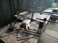
...but, during re-assembly...a Duck...kinda...got in the way :ack2:
SAM_4860.JPG
Um...hello?
...I'ma workin' here :huh:

Ducky thinkin'
..."Don't Care"
...& you should probably pet my 'wittle head, about...now :smartass:
SAM_4861 (1).JPG
After a bit of head rubbin'
...she went about her business
&
I got the wheels on
...got 'er off the workbench
...& then, did a "weight" test, with driver (me)
&
These (V2) coil-over shocks, seem to "carry the load" better
But,
This "test" revealed another "issue"

I can see the upper frame rail "flexing"

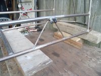
I had "in mind" to add some "braces"
...in between the frame rails
...to kinda "tie 'em together"
...& strengthen them
So
I guess we should do that...now

Maybe something like this :thumbsup:
SAM_4863 (1).JPG
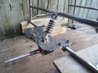
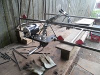
Did a quick mockup with the coil-overs & motor
...ta make sure everything "works together" :cheers2:
* Check out that "3-way triangulation" :sifone:
...kinda like little Pyramids
SAM_4862 (1).JPG
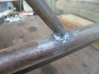
Welded 'em on good-n-strong :2guns:
SAM_4864 (1).JPG
Close up
SAM_4865 (1).JPG
 
Top