Functional Artist
Well-known member
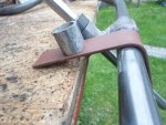
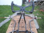
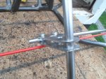
I believe it’s to allow more chassis flex for more grip. Glexis a big part of handling on race karts. We spend a lot of time making sure that nerf bars, seats, and bumpers fit without binding since that affects flex and handling.
I was joking about the competitive thing, I think it’s cool that you’re building one of these yourself.
Thanks, that's what I kinda figured

More info in this "Glexis" stuff please

I tried Google-in' it

...but didn't find anything

I had ta design & build my own (it's kinda "my thing")

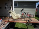
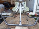
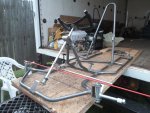
Converting a kart from gas to electric isn't that hard
...the main issue is where to put them batteries (the bat pack)
So, IMO a custom design is the "best" way to go

...designed around the major components
…& also, you have more flexibility on where ya can place stuff
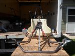
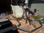
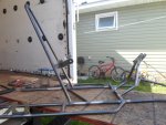
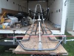
Ima gonna try a few (many) things out on this "test kart"
...then, maybe make another one out of lighter materials
...plus, anything I learn from this one/these tests

Um...don't chicken out, on me now

…"I'm comin' for you"