2019 - New GrandDaddy build (contd 2018)

Status
Not open for further replies.

pa17315

Member
Messages
151
Reaction score
0
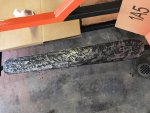
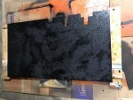
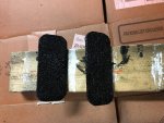
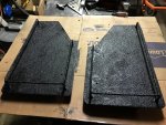
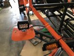
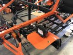
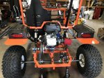
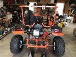
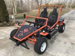
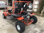
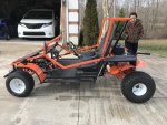
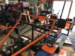
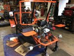
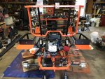
2019 Front and Rear mud/guards painted

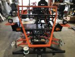
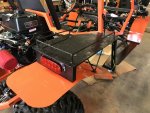
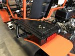
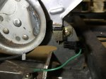
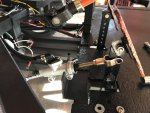
This is how it looks. I have waited a long time to see the final results. There are times I am even sure that it would look right or even work out as I have hoped.
 

Attachments

  • IMG_1103.jpg
    IMG_1103.jpg
    419 KB · Views: 12
  • IMG_1104.jpg
    IMG_1104.jpg
    381.7 KB · Views: 12
  • IMG_1105.jpg
    IMG_1105.jpg
    358.8 KB · Views: 11
  • IMG_1106.jpg
    IMG_1106.jpg
    334.8 KB · Views: 11
  • IMG_1107.jpg
    IMG_1107.jpg
    438.6 KB · Views: 12
  • IMG_1109.jpg
    IMG_1109.jpg
    394.9 KB · Views: 12
  • IMG_1108.jpg
    IMG_1108.jpg
    416.2 KB · Views: 10

pa17315

Member
Messages
151
Reaction score
0
2019 Update

Couple of things I will work on next to finish this mud/guard series.

Metal plate on the rear mudguard

Finish putting Herculiner on running boards
 

pa17315

Member
Messages
151
Reaction score
0
2019 Running boards part 2

Preparing running boards for Herculiner application. Existing gray protective layer on metal is very hard to take off. 60 grids sander flap, and paint grinder wheel did not take it off. I have ended up using metal grinder disc to scuff the metal surface.
 

Attachments

  • IMG_1121.jpg
    IMG_1121.jpg
    357.8 KB · Views: 5
  • IMG_1123.jpg
    IMG_1123.jpg
    325.3 KB · Views: 5

pa17315

Member
Messages
151
Reaction score
0
2019 Running boards part 3

Applied herculiner on running board (2) days ago. It is still tacky. The weather has hovered around high 20 degree to 40 degree Fahrenheit during the last few days. I have started to think about wiring signal lights in the mean time.
 

Attachments

  • IMG_1128.jpg
    IMG_1128.jpg
    435.6 KB · Views: 8
  • IMG_1127.jpg
    IMG_1127.jpg
    414.8 KB · Views: 10
  • IMG_1126.jpg
    IMG_1126.jpg
    390.8 KB · Views: 6
  • IMG_1125.jpg
    IMG_1125.jpg
    409.5 KB · Views: 8
  • IMG_1124.jpg
    IMG_1124.jpg
    376.8 KB · Views: 7

pa17315

Member
Messages
151
Reaction score
0
2019 Floor steel plate

Prepared and applied Herculiner on the floor plate, pedals and carrier
 

Attachments

  • IMG_1136.jpg
    IMG_1136.jpg
    478.3 KB · Views: 3
  • IMG_1135.jpg
    IMG_1135.jpg
    392.1 KB · Views: 4
  • IMG_1137.jpg
    IMG_1137.jpg
    668.7 KB · Views: 4

pa17315

Member
Messages
151
Reaction score
0
2019 Propane heater for cold weather.

After looking around to find an alternative solution to heat the work area in the garage, I have settled on Dewalt propane heater. This baby puts out a lot of heat from 27,000 to 68,000 BTU. Other options from kerosene, to radiating units atop of propane tank did not appeal to me. They were either fire hazards or too much fume.
 

Attachments

  • IMG_1133.jpg
    IMG_1133.jpg
    237.3 KB · Views: 4
  • IMG_1134.jpg
    IMG_1134.jpg
    229 KB · Views: 4

pa17315

Member
Messages
151
Reaction score
0
2019 Turn Signals part 1

Here is the diagram for the turn signal that I have chosen for my go kart.

Originally, I was using 7 pins on-off-on switch in place of go kart signal switch. However, for my go kart, it is better suited for a switch. Along the way, I have misplaced the switch and bought new one from Amazon. Unintentionally, it has only 4 pins. That would also work and it would be easier to wire.

On my go kart, two front and rear signals. Additional side turn signals to provide reference for the driver.

Signal switch mounted on main control area. Other options were considered such as on steering wheel, on the side.

On the steering wheel, it is too cumbersome and I have to deal with wires when taking the wheel on and off.

On the side mount where is it easily accessible to the driver would also become another obstacle when getting in and out of the go-kart.

Eventually, mounting on the main control is out of the way and it is only to be used when I turn on the road.
 

Attachments

  • IMG_1140.jpg
    IMG_1140.jpg
    290.9 KB · Views: 5
  • IMG_1138.jpg
    IMG_1138.jpg
    335.6 KB · Views: 4
  • 4 pins wire signal connection.jpg
    4 pins wire signal connection.jpg
    121.7 KB · Views: 4
  • 7 pins wire signal connection.jpg
    7 pins wire signal connection.jpg
    138.1 KB · Views: 5

pa17315

Member
Messages
151
Reaction score
0
2019 Turn Signals part 2

Lights signals are mounted. 4 inches front amber signal lights and 8 inches rear red signal lights are mounted. Additional bullet shaped light signals for front and rear are mounted under the side mirrors for the front and on roll cage frame for the rear. These bullet shaped amber signals have blue LED lights in the back of the units that turn on when activated.
 

Attachments

  • IMG_1151.jpg
    IMG_1151.jpg
    368.5 KB · Views: 6
  • IMG_1149.jpg
    IMG_1149.jpg
    381.7 KB · Views: 6
  • IMG_1146.jpg
    IMG_1146.jpg
    351.5 KB · Views: 5
  • IMG_1148.jpg
    IMG_1148.jpg
    289.4 KB · Views: 6
  • IMG_1147.jpg
    IMG_1147.jpg
    347.8 KB · Views: 6
  • IMG_1145.jpg
    IMG_1145.jpg
    402.1 KB · Views: 8

pa17315

Member
Messages
151
Reaction score
0
2019 brake light part 1

Brake light connection is mounted on the roll cage. It is connected from the battery to hydraulic brake switch. Every time the brake is applied, the light would turn on.

Eventually, I would like to connected onto the emergency brake lever as well. I haven't done any research yet.
 

Attachments

  • IMG_1150.jpg
    IMG_1150.jpg
    407.1 KB · Views: 5
  • IMG_1152.jpg
    IMG_1152.jpg
    245.3 KB · Views: 7

pa17315

Member
Messages
151
Reaction score
0
2019 brake light part 2

I did some research today where brake light is activated by brake pedal or emergency brake lever.

The issue is how to prevent current flowback since you have two switches. Sometime back I have to build an remotely operated chicken door with diode and switches. There are two shut off switch at full opening and at closing. To prevent and separate DC current, a diode was used.

This is basically the same concept so I have sketched up a wire connection diagram. In theory, when I step on the brake pedal, the light would come on. With additional diodes at each switch, the DC current is only going in one direction.

I will test this out to see if it works.
 

Attachments

  • BRAKE LIGHT CONNECTIONl.jpg
    BRAKE LIGHT CONNECTIONl.jpg
    137.1 KB · Views: 3

pa17315

Member
Messages
151
Reaction score
0
2019 brake light part 3

I have checked my emergency brake lever and setup is different. On my lever, the switch is controlling the ground.

Here is an update pic. Hopefully, I can test it out before final connection.
 

Attachments

  • BRAKE LIGHT CONNECTION 2.jpg
    BRAKE LIGHT CONNECTION 2.jpg
    140.3 KB · Views: 5
  • IMG_1156.jpg
    IMG_1156.jpg
    202.8 KB · Views: 4
  • IMG_1154.jpg
    IMG_1154.jpg
    243.3 KB · Views: 4
  • IMG_1153.jpg
    IMG_1153.jpg
    249.9 KB · Views: 5

pa17315

Member
Messages
151
Reaction score
0
2019 Go-kart completion

I hope this is done!
 

Attachments

  • IMG_1193.jpg
    IMG_1193.jpg
    482.7 KB · Views: 18
  • IMG_1192.jpg
    IMG_1192.jpg
    548.4 KB · Views: 16
  • IMG_1191.jpg
    IMG_1191.jpg
    504.1 KB · Views: 16
  • IMG_1190.jpg
    IMG_1190.jpg
    527.5 KB · Views: 17
  • IMG_1189.jpg
    IMG_1189.jpg
    481.9 KB · Views: 14
  • IMG_1194.jpg
    IMG_1194.jpg
    495.7 KB · Views: 17
  • IMG_1195.jpg
    IMG_1195.jpg
    511.1 KB · Views: 23

pa17315

Member
Messages
151
Reaction score
0
Dang it looks awesome!!!!! :wai::wai:

Well done! Have you ridden it much now?

Thanks, It is looking nice.

I took it for a drive the other day and something else come up. The brake pedal is so stiff, it doesn't plunge as far as I can press it. I have taken it apart to look at it.

I will post when I have figured out the problem.

Darn, I thought I was.....done!!!!!
 

pa17315

Member
Messages
151
Reaction score
0
2019 Hydraulic brake master cylinder part 1

I have a problem with the master cylinder. Initially, I have purchased a brake kit from Ebay. It has rear and front brake calipers and a master cylinder.

I did not use the front brake so I have capped the port 1 and 2 on the master cylinder. Port 3 was routed to the rear brake caliper. Plunger rods for right and left port was used and connected to the brake pedal.

Since both plunger was used and port 1 and 2 was capped, pressure as build up over time until I cannot press the plunger any further.

I have removed the master cylinder and remove the bolts on port 1 and 2. Sure enough, I can press the plunger again.


Next problem is figure out which plunger port, the right or left activate the hydraulic pressure switch.

Here is the break down:

Right plunger port services Hydraulic pressure switch and port 1. On the picture post below with wire sticking out

Left plunger port services port 2 and 3

I am going to cap port 2 and 3, use only one plunger for right plunger port and see if it works.

There is an alternative that I am also pursuing.
 

Attachments

  • IMG_1196.jpg
    IMG_1196.jpg
    404 KB · Views: 3
  • IMG_1197.jpg
    IMG_1197.jpg
    328 KB · Views: 3
  • IMG_1198.jpg
    IMG_1198.jpg
    313.8 KB · Views: 3
  • s-l1600a.jpg
    s-l1600a.jpg
    281.2 KB · Views: 3

pa17315

Member
Messages
151
Reaction score
0
2019 Hydraulic brake master cylinder part 2

There is an alternative for master cylinder. My brother has used motorcycle brake hydraulic cylinder for his go kart. There are advantages such as cost and easy to purchase on Amazon or Ebay.

I bought mine from Amazon for about 14 bucks and another 8 for the hydraulic brake switch.
 

Attachments

  • M10 x 1.25 Pitch Hydraulic Brake Light Switch.jpg
    M10 x 1.25 Pitch Hydraulic Brake Light Switch.jpg
    79.5 KB · Views: 2
  • Motorcycle Rear Master Cylinder With Reservoir.jpg
    Motorcycle Rear Master Cylinder With Reservoir.jpg
    65.8 KB · Views: 2

pa17315

Member
Messages
151
Reaction score
0
2019 Hydraulic brake master cylinder part 3

Some pics of the new master cylinder on my go kart.

Fabrication next
 

Attachments

  • IMG_1199.jpg
    IMG_1199.jpg
    353.1 KB · Views: 5
  • IMG_1200.jpg
    IMG_1200.jpg
    349.5 KB · Views: 3
  • IMG_1201.jpg
    IMG_1201.jpg
    337.4 KB · Views: 4
  • IMG_1209.jpg
    IMG_1209.jpg
    163.1 KB · Views: 3

pa17315

Member
Messages
151
Reaction score
0
Spoindle

Does anyone know where I can get this part? and what is it called?

Thanks
 

Attachments

  • spindle.png
    spindle.png
    167.9 KB · Views: 9
Status
Not open for further replies.
Top