2017 - El Turbo OD/OV

Status
Not open for further replies.

Functional Artist

Well-known member
Messages
5,576
Reaction score
3,168
Location
Toledo, Ohio
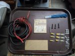
Piece of Lexan

3/16 nuts & bolts

3/16" crimp ends

30A fuse/holder/wire/loom

& a little spring action

:cheers2:
 

Attachments

  • SAM_3496.jpg
    SAM_3496.jpg
    248.5 KB · Views: 15

Dmehalko

New member
Messages
25
Reaction score
0
What are you going to turbo? Ill hopefully have my Ecotrons kit here shortly for my shopping cart project
 

Functional Artist

Well-known member
Messages
5,576
Reaction score
3,168
Location
Toledo, Ohio
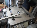
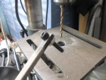
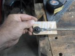
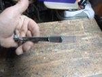
Drilled a 3/16" hole near the end of a 3/16" x 3/8" x 6" piece of steel.

added a 3/16" x 1" Allen head bolt with nut. (pivot point)

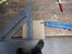
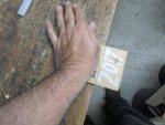
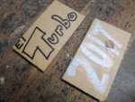
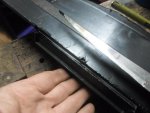
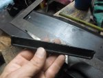
Scribed the Lexan on both sides & snapped off nice-n-clean (top-n-bottom)
 

Attachments

  • SAM_3488.jpg
    SAM_3488.jpg
    233.2 KB · Views: 4
  • SAM_3492.jpg
    SAM_3492.jpg
    235.1 KB · Views: 4
  • SAM_3504.jpg
    SAM_3504.jpg
    279.9 KB · Views: 4
  • SAM_3505.jpg
    SAM_3505.jpg
    236.9 KB · Views: 4
  • SAM_3506.jpg
    SAM_3506.jpg
    250 KB · Views: 6

Functional Artist

Well-known member
Messages
5,576
Reaction score
3,168
Location
Toledo, Ohio
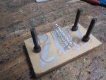
The contact/terminals are to be arranged roughly as such

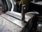
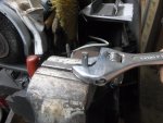
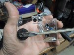
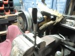
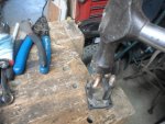
Clamped the lever (3/16" x 3/8" steel) squarely (90*) into vise

Used an adjustable wrench to giver' a nice little twist

Came across a plastic washer with a 3/16" hole & a 3/8" step up

Mounted the lever/washer to left lower corner of the back plate

That should do for a pivot point
 

Attachments

  • SAM_3512.jpg
    SAM_3512.jpg
    262.5 KB · Views: 4
  • SAM_3510.jpg
    SAM_3510.jpg
    221.5 KB · Views: 5
  • SAM_3509.jpg
    SAM_3509.jpg
    237.5 KB · Views: 4
  • SAM_3508.jpg
    SAM_3508.jpg
    237.4 KB · Views: 5

Functional Artist

Well-known member
Messages
5,576
Reaction score
3,168
Location
Toledo, Ohio
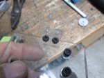
Drilled a couple of 3/16" holes & mounted the contact terminals

Added a small plastic L for a spring bracket

For this crude experiment I am just using regular old steel

...for the lever

...& the nuts & bolts I am using as contact terminals

Not really recommended for conducting electricity

well but.... lets roll with it :2guns:

Cut some spacers from these ah...things to add the top plate

Yup! :thumbsup:

Kinda, roughly what I had in mind.
 

Attachments

  • SAM_3515.jpg
    SAM_3515.jpg
    197.5 KB · Views: 4
  • SAM_3513.jpg
    SAM_3513.jpg
    274.7 KB · Views: 4
  • SAM_3517.jpg
    SAM_3517.jpg
    229.6 KB · Views: 4

Functional Artist

Well-known member
Messages
5,576
Reaction score
3,168
Location
Toledo, Ohio
If this thing works...

when the propulsion system is functioning normally there should be 24 volts running thru the lever

when our Turbo is engaged there should be 36 volts running thru it.

so, lets add some insulation

*In hind sight, this isn't the greatest idea to have the current actually running thru the lever itself but, using steel contact hardware wasn't either

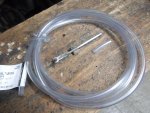
...slid a ~2" piece of vinyl tubing over the end of the lever

then, to double up the protection, don't wanna get zapped :thumbsup:

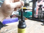
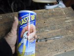
I am gonna dip the end into some rubber tool handle dip -red Turbo lever will look kool :2guns:

Ug, dried up, plan B, liquid rubber tape -black Turbo lever will look kool too
 

Attachments

  • SAM_3529.jpg
    SAM_3529.jpg
    256.8 KB · Views: 3
  • SAM_3527.jpg
    SAM_3527.jpg
    243.6 KB · Views: 3
  • SAM_3524.jpg
    SAM_3524.jpg
    292.1 KB · Views: 3
  • SAM_3522.jpg
    SAM_3522.jpg
    252.4 KB · Views: 3
  • SAM_3518.jpg
    SAM_3518.jpg
    306.9 KB · Views: 3

Functional Artist

Well-known member
Messages
5,576
Reaction score
3,168
Location
Toledo, Ohio
To wire this thing up...

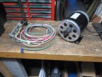
...attached a length of 14g. wire (green) w/ring terminal running from the fulcrum of the Turbo switch to the (+) input to the motor

...attached a similar length of wire (white) running from the lower contact terminal of the switch to the (+) out put coming from the speed controller

...& attached another wire (red) running from the top terminal of the switch to the (+) terminal coming from a third 12 volt battery wired in series with our original (2) 12 volt batteries

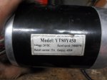
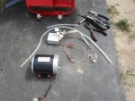
For these initial experiments/tests I am using a little YT80Y450 24V 450W brushed DC motor

(let's start off small 24V to 36V @ ~25-30 amps to be safe-er)

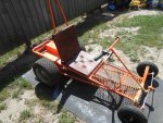
This is one of the motors off of the Double Trouble Kart

I wasn't impressed with the additional power from adding a second motor

but, if you think about it

...if the motor your using has a top rpm speed of 2,500

...then adding another motor with the same top rpm speed would only make up for losses (help carry the load) NOT increase speed

Back to this...

(2) 12V batteries wired in series (24V) are needed to power this motor & speed controller

...wired a third 12V battery in series (providing 36V) to power the Turbo switch

So, The standard drive line is wired

...(24V+) power comes from the first 2 batteries to the speed controller, from there, goes thru the Turbo switch (normal rested position) & to (+) input of the motor

The theory is...

Start off & drive normally as if the Turbo switch wasn't even there (top motor rpm 2,500)

Then hit the switch (lever) & it disconnects the speed controller (so we don't back feed 36V back thru it :ack2: )

& instantly sends 36V (a theoretical 1,250.04 rpm boost) straight to the motor :2guns:

https://www.youtube.com/watch?v=jQ_L0QKPUOk
 

Attachments

  • SAM_3579.jpg
    SAM_3579.jpg
    292.4 KB · Views: 3
  • SAM_3578.jpg
    SAM_3578.jpg
    181.1 KB · Views: 3

Functional Artist

Well-known member
Messages
5,576
Reaction score
3,168
Location
Toledo, Ohio
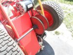
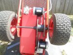
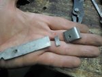
Now to harvest the motor off of Double Trouble

Unbolted rear motor, speed controller, left thumb throttle & associated wiring

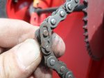
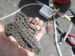
Now to remove second chain

Don't need that floppin' around

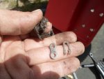
Found master link

slide to unlock

remove chain

reassemble for future use :thumbsup:

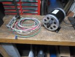
The (2) motor's & speed controllers are identical

so I am gonna use the removed motor for bench testing

& if we get that far

the other motor is still mounted/wired/ ready to go

just, add Turbo switch & reconfigure some wiring

& start testing

First, I'm a gonna do a couple of runs with the standard stock configuration, to establish/record top speed data

Then, we'll add the switch :2guns:
 

Attachments

  • SAM_3541.jpg
    SAM_3541.jpg
    200.9 KB · Views: 2
  • SAM_3540.jpg
    SAM_3540.jpg
    371.2 KB · Views: 2
  • SAM_3537.jpg
    SAM_3537.jpg
    357.3 KB · Views: 3
  • SAM_3535.jpg
    SAM_3535.jpg
    370.4 KB · Views: 5
  • SAM_3533.jpg
    SAM_3533.jpg
    535.8 KB · Views: 5
  • SAM_3542.jpg
    SAM_3542.jpg
    252.4 KB · Views: 3
  • SAM_3543.jpg
    SAM_3543.jpg
    220.3 KB · Views: 3
  • SAM_3544.jpg
    SAM_3544.jpg
    325.3 KB · Views: 2

Functional Artist

Well-known member
Messages
5,576
Reaction score
3,168
Location
Toledo, Ohio
Well, Back to the drawing board! :idea2:

It seem that a (or this) speed controller operates by intermittently chopping the (-) ground going to the motor.

Not the (+) positive.


*This means that when the controller is on it sends full power (+) to the motor constantly

So,when the throttle is at rest there is no ground (-) going to the motor.

When the throttle is twisted (activated) a little, it only connects the ground (-) for a few milliseconds at a time.

As you twist more, the ground (-) is applied for longer amounts of time.

So, full speed should be 100% (+) & 100% (-) going to motor.

I think that's why, when I checked with the meter there was full voltage going to the motor regardless of the throttle position.


So, lets try a building a switch that breaks both circuits. :thumbsup:

Also, while were at it lets try to use better conductive materials for the contactors.

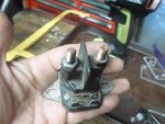
I have a few solenoids off old riding mowers.

Lets open them up & harvest some stuff. :2guns:
 

Attachments

  • SAM_3598.jpg
    SAM_3598.jpg
    224.3 KB · Views: 3
  • SAM_3597.jpg
    SAM_3597.jpg
    258.4 KB · Views: 3
  • SAM_3596.jpg
    SAM_3596.jpg
    236.5 KB · Views: 3
  • SAM_3594.jpg
    SAM_3594.jpg
    253.4 KB · Views: 3
  • SAM_3591.jpg
    SAM_3591.jpg
    243.7 KB · Views: 3

Functional Artist

Well-known member
Messages
5,576
Reaction score
3,168
Location
Toledo, Ohio
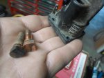
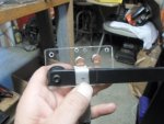
Dismantled the switch to start over.

This time I'm a gonna use a

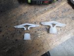
...plastic lever (safer) (cut off old TV back)

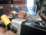
...more proper contact terminals (brass) (from lawnmower solenoid)

I couldn't find a piece of flat copper or brass layin' around but, I found a piece of aluminum gutter strap, should be conductive.

Mounted plastic lever in same hole as before.

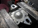
Drilled out contactor holes & second set of holes in the back of the switch plate to fit the new hardware.

Cut a couple pieces from the aluminum strap, drilled hole for ring terminal & then bent them @ a 90* angle to fit nicely over lever.
 

Attachments

  • SAM_3602.jpg
    SAM_3602.jpg
    238.1 KB · Views: 3
  • SAM_3600.jpg
    SAM_3600.jpg
    280 KB · Views: 3
  • SAM_3603.jpg
    SAM_3603.jpg
    246.3 KB · Views: 3
  • SAM_3612.jpg
    SAM_3612.jpg
    189.7 KB · Views: 3
  • SAM_3610.jpg
    SAM_3610.jpg
    196.3 KB · Views: 3

Functional Artist

Well-known member
Messages
5,576
Reaction score
3,168
Location
Toledo, Ohio
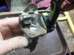
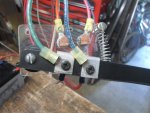
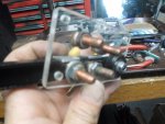
Got all (4) contact terminals & lever installed.

Took a bit of work to get everything lined up, to make contact evenly.

Well that should work. :thumbsup:
 

Attachments

  • SAM_3622.jpg
    SAM_3622.jpg
    248.3 KB · Views: 3
  • SAM_3617.jpg
    SAM_3617.jpg
    208.4 KB · Views: 3
  • SAM_3615.jpg
    SAM_3615.jpg
    232.4 KB · Views: 3

Functional Artist

Well-known member
Messages
5,576
Reaction score
3,168
Location
Toledo, Ohio
Got Turbo Switch 2 assembled

lets wire it up. :thumbsup:

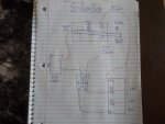
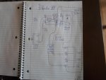
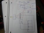
First diagram is how switch #1 was wired.

Second diagram is for switch #2

As I said,

...the first switch only affected the positive (+) circuit going from the speed controller to the motor.

...the second switch simultaneously breaks both the positive (+) & negative (-) circuits (separately) going from speed controller to the motor.

...& allows simultaneous (separated) contact with both a 36V positive (+) & a negative (-) straight from battery pack to the motor.

The (2) wires connected to the lever & the aluminum contactors w/ring terminals are (green) Positive (+) & (blue) negative (-), they send the power to the motor.

So, which ever terminals they are in contact with (lower 24V from speed controller & upper 36V from battery pack) that power goes to the motor.

The lower contact terminals have (red) positive (+) & (white) negative (-) wires connected w/ring terminals, that bring the power from the speed controller to the switch

The upper contact terminals have (pink) positive (+) & (orange) negative (-) wires connected w/ring terminals, that bring the power from the battery pack

Should work. :2guns:

...on to testing.

https://www.youtube.com/watch?v=GG5FDEoV6sI&t=394s
 

Attachments

  • SAM_3654.jpg
    SAM_3654.jpg
    220 KB · Views: 3
  • SAM_3656.jpg
    SAM_3656.jpg
    218.1 KB · Views: 4

Functional Artist

Well-known member
Messages
5,576
Reaction score
3,168
Location
Toledo, Ohio
Well, its gonna be...

One of those days. :huh:

Found the problem :wai:

During my ride,

the plastic connector, connecting the speed controller wire harness to the motor wire harness got hot & melted. (enough that the positive (+) spade connectors separated)

Was difficult to get apart all deformed -n- stuff.

Cut off bad plastic parts,

was able to save the spade connectors

hooked 'er back together

soldered both connections

Boom! :2guns:

Back-n-business!

Now we can resume our ride. :thumbsup:

https://www.youtube.com/watch?v=6h7uUBaefQI&feature=em-upload_owner

Now, takin' wife & kids downtown for fireworks :thumbsup:

Happy 4th everyone :cheers2:
 
Last edited:

Kbosher

Kevin
Messages
11
Reaction score
0
Location
Farmville
U need a pulse with modulator that is capable of the output voltages you are trying to acheive most cam and crank sensors on todays automotive motors work with that technology. I have some that i bought online for around 20 dollars but there output is limited with 12v in 5v out square wave just read the input and output rates mot work on a potentiometer design...some work with a digital output but would be harder to output by a pedal

Sent from my SM-N920V using Tapatalk
 

Functional Artist

Well-known member
Messages
5,576
Reaction score
3,168
Location
Toledo, Ohio
Back to the drawin' board.

I like my drawin' board. :thumbsup:

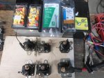
Rounded up some more lawn mower solenoids.

Runnin' low on wire & crimp ends.

Home Depot run :auto:

For a more proper set up

I got some;

...10g. red & black stranded wire

...some 10-12g. 1/4" ring terminals

...some 10-12 g. female spade connectors.

...shrink wraps & little wire ties

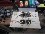
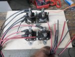
Got the (4) solenoids layed out on a piece of board.

the left (2) solenoids will be for the 24V side & the right (2) are for the 36V side

To clarify & help make sure I wire this thing up right, I marked everything right on the board
(what does what & what goes where)

So, now to get started

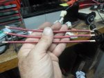
...measured & cut (2) 24" pieces of the red 10g. (positive (+) cables)

...& (2) pieces of the black (negative (-) cables)

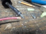
...stripped ~1/4" of insulation off the end of the wires

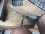
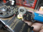
...first slid on a piece of shrink wrap

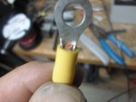
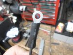
...insert the stripped end of a wire into a crimp end until the end is just visible

...use proper slot in crimper tool to crimp the end on to the wire

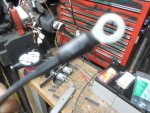
...slide shrink wrap up over connection evenly so it will seal up both ends when shrunk

Yup, that should do.

repeated several times, with which ever type of end that matched up with the connector that it was being attaching to
 

Attachments

  • SAM_3682.jpg
    SAM_3682.jpg
    300.5 KB · Views: 3
  • SAM_3680.jpg
    SAM_3680.jpg
    284.2 KB · Views: 3
  • SAM_3679.jpg
    SAM_3679.jpg
    247.2 KB · Views: 3
  • SAM_3678.jpg
    SAM_3678.jpg
    252.3 KB · Views: 4
  • SAM_3676.jpg
    SAM_3676.jpg
    310.9 KB · Views: 3
  • SAM_3685.jpg
    SAM_3685.jpg
    182.9 KB · Views: 3
  • SAM_3686.jpg
    SAM_3686.jpg
    246.1 KB · Views: 3
  • SAM_3688.jpg
    SAM_3688.jpg
    210.5 KB · Views: 3
  • SAM_3691.jpg
    SAM_3691.jpg
    303.6 KB · Views: 3

Functional Artist

Well-known member
Messages
5,576
Reaction score
3,168
Location
Toledo, Ohio
U need a pulse with modulator that is capable of the output voltages you are trying to acheive most cam and crank sensors on todays automotive motors work with that technology. I have some that i bought online for around 20 dollars but there output is limited with 12v in 5v out square wave just read the input and output rates mot work on a potentiometer design...some work with a digital output but would be harder to output by a pedal

Sent from my SM-N920V using Tapatalk

Thanks,

I'll look into it if my ideas don't work out. :thumbsup:
 

Functional Artist

Well-known member
Messages
5,576
Reaction score
3,168
Location
Toledo, Ohio
Now, to wire this thing up (hey, haven't I said that before?)

The speed controller is hooked like normal except,

...output goin' to motor is diverted to the solenoids on the left side of the board

Turbo is hooked up like before,

with the positive (+) & negative (-) cables goin to the solenoids on the right

So, when the Turbo switch is used

...wichever solenoids are turned on at the time (left bank or right bank) will send its positive & negative to the motor while simultaneously turning the other solenoids off, preventing a power feedback situation

I soldered & shrunk wrapped the power & negative cables, from each circuit 24V & 36V where I connected them, just before the motor

From my research, I have found that

...it is best to use ALL the same type/kind of connectors & the same lengths connector cables when building a battery pack (for resistance)

...and when wiring motors & controllers, it's best to use the same size wire as used on the motor & controller (again resistance)

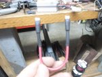
So, I made some more proper battery connector cables (connects from battery to battery)

Now, ALL cables for the motor, controller & battery connections are the same (10g. wire) as the wires, coming from the speed controller & goin' to the motor. :thumbsup:
 

Attachments

  • SAM_3699.jpg
    SAM_3699.jpg
    300.4 KB · Views: 4
  • SAM_3697.jpg
    SAM_3697.jpg
    212.9 KB · Views: 3
  • SAM_3695.jpg
    SAM_3695.jpg
    287.8 KB · Views: 3
  • SAM_3708.jpg
    SAM_3708.jpg
    226.6 KB · Views: 3
  • SAM_3710.jpg
    SAM_3710.jpg
    245.4 KB · Views: 3
  • SAM_3718.jpg
    SAM_3718.jpg
    202.4 KB · Views: 4
Status
Not open for further replies.
Top