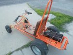
2017 - El Turbo OD/OV

Status
Not open for further replies.

Functional Artist

Well-known member
Messages
5,559
Reaction score
3,149
Location
Toledo, Ohio
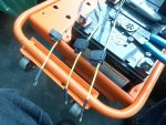
Workin' on gettin' everything wired up

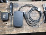
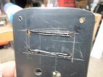
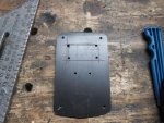
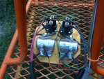
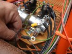
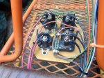
solenoid panel is done

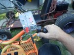
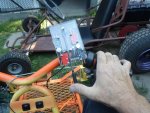
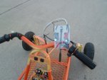
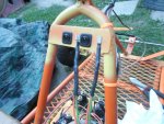
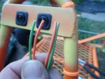
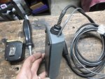
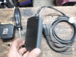
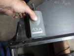
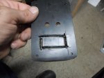
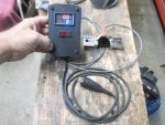
Turbo switch is done (I broke a small piece out of the back plate while drilling the last mounting hole)

it should still be OK

Installed it on the handle bar, right next to the thumb throttle

So you can go from normal drive to Turbo with out much extra effort

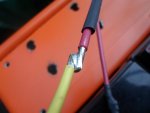
Soldered in (3) fuse holders to protect the circuits

Batteries are all hooked up

That looks like everything

Time for a system check

https://www.youtube.com/watch?v=RW1DhH3DfVU
 

Attachments

  • SAM_4090.jpg
    SAM_4090.jpg
    213.2 KB · Views: 3
  • SAM_4095.jpg
    SAM_4095.jpg
    338.3 KB · Views: 3
  • SAM_4096.jpg
    SAM_4096.jpg
    334.4 KB · Views: 3
  • SAM_4100.jpg
    SAM_4100.jpg
    124 KB · Views: 3
  • SAM_4099.jpg
    SAM_4099.jpg
    324.6 KB · Views: 4

Functional Artist

Well-known member
Messages
5,559
Reaction score
3,149
Location
Toledo, Ohio
All systems seemed to operate as designed :thumbsup:

The solenoids kick on & off properly, so the 12V circuit checks out

The thumb throttle operates the speed controller normally, so the 24V circuit checks out

& the Turbo kicked in big time, so

Yup, that works too! :2guns:


Well, time for some real world testing

https://www.youtube.com/watch?v=wcMomYC80UE&t=259s
 

Attachments

  • SAM_4115.jpg
    SAM_4115.jpg
    228.3 KB · Views: 2
  • SAM_4111.jpg
    SAM_4111.jpg
    410.6 KB · Views: 2
  • SAM_4113.jpg
    SAM_4113.jpg
    334.4 KB · Views: 2
  • SAM_4112.jpg
    SAM_4112.jpg
    335.9 KB · Views: 2

Functional Artist

Well-known member
Messages
5,559
Reaction score
3,149
Location
Toledo, Ohio
Well,

12V system functions

24V system functions (except for the solenoids actin' up, kinda expected)

36V system (let's just say, it's a work in progress)

When it kicked in, it kicked in hard (as expected) :2guns:

but, the 30 amp fuse couldn't handle it

it blew very HARD (totally blackened)

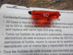
I guess we'll try a 40 amp fuse

if that don't do it, we'll have to look for something BIGGER

I noticed on the package "up to 32Vdc"

...maybe that's the problem

I guess were moving out of the realm of where (some) automotive stuff is usable (or it at least needs to be factored into the equation)
 

Attachments

  • SAM_4155.jpg
    SAM_4155.jpg
    226.1 KB · Views: 1

Bbqjoe

Banned
Messages
3,455
Reaction score
67
Location
Location, Location
And I went down to the demonstration
To get my fair share of abuse
Singing, "We're going to vent our frustration
If we don't, we're going to blow a 50-amp fuse"
 

Functional Artist

Well-known member
Messages
5,559
Reaction score
3,149
Location
Toledo, Ohio
Went to do another test run

...to see if, moving up to, a 40 amp fuse can handle our 36V jolt of power

but, them intermittent duty solenoids, I used, are NOT cooperating

we need constant duty solenoids for the 24V circuit

...because it's used almost the whole time the karts running.

The (2) for our 36V Turbo should last a while

...because were only using them intermittently like they were designed for.

https://www.youtube.com/watch?v=mdNWqYzCs3U&t=8s
So, I ordered (2) constant duty solenoids

should be here in a few days

Test is on hold til then :ack2:
 

Functional Artist

Well-known member
Messages
5,559
Reaction score
3,149
Location
Toledo, Ohio
While waitin' on the constant duty solenoids I ordered,

I think we need to re-work the solenoid circuit.

The way things are set up now,

...the positive (+) of ALL (4) solenoids are wired together & go straight to the 12V battery positive (+)

...the (2) 24V solenoid's negatives (-) are wired together then go to a switch on the dash board, (so I can turn them off) then go to the 24V micro switch, then to the negative (-) of the battery.

Because of the way the Turbo switch is set up, the solenoids would be powered "on" constantly & only shut off when turbo was engaged

but, (for overheating purposes) we really, don't want them on constantly, only when needed. (so I added a switch)

...& the (2) 36V solenoid's negatives (-) are wired together then go to the 36V micro switch, then straight to the battery positive (+) (NOT switched)

I didn't think they needed to be switched because their only used occasionally

but, as we found, if it's not switched & YOU BUMP IT-YOU WILL BLOW THE FUSE-EVERYTIME)


So, I think I got a (revised) plan :thumbsup:


This time,

...the (4) positive's (+) are still wired together but, then go to the switch on the dash, then go to the 12V battery positive (+)

...the (2) 24V solenoids negatives (-) are wired together then go to the 24V micro switch, then go to the negative of the battery.

...& the (2) 36V solenoids negatives (-) are wired together then go to the 36V micro switch, then go to the negative of the battery.


So now, the main switch controls the positive circuit & the Turbo switch controls the negative circuit of the solenoids.
 

Attachments

  • SAM_4199.jpg
    SAM_4199.jpg
    226.3 KB · Views: 1
  • SAM_4197.jpg
    SAM_4197.jpg
    218.4 KB · Views: 1

Kansaskart

New member
Messages
452
Reaction score
9
Pretty cool. Reminds me to order an electronics course so I can make even more of my whacked out ideas a reality.
 

Functional Artist

Well-known member
Messages
5,559
Reaction score
3,149
Location
Toledo, Ohio
Got the solenoid circuit switches around :thumbsup:

First, made sure the positive (+) wires would reach up to the on/off switch

...clipped them @ the top of the loop

...slid on some heat shrink & crimped on some spade terminals

For the negative (-) side that used to go to the switch

...just had to clip off the spade terminals

...& slide on some heat shrink

...& solder them together

Boom! like it never even happened

Now, the positive's (+) for ALL solenoids shut off with the on/off switch

...& the negative's (-) are still wired thru the Turbo switch, like before
 

Attachments

  • SAM_4220.jpg
    SAM_4220.jpg
    323.2 KB · Views: 1
  • SAM_4231.jpg
    SAM_4231.jpg
    377.6 KB · Views: 1
  • SAM_4223.jpg
    SAM_4223.jpg
    192.9 KB · Views: 1
  • SAM_4222.jpg
    SAM_4222.jpg
    250.1 KB · Views: 1
  • SAM_4221.jpg
    SAM_4221.jpg
    335.2 KB · Views: 1

Functional Artist

Well-known member
Messages
5,559
Reaction score
3,149
Location
Toledo, Ohio
Workin' on another project to use on this project

Seems like I'm always workin in on a project within a project

So, I rounded up some stuff

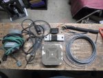
... a really old smoke detector

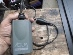
...a broken aquarium air pump

...a circuit tester (blown bulb)

...& some wire


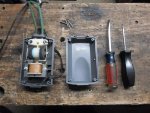
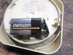
Opened up the smoke detector & removed the hook-up w/wires for the 9V battery

...opened up the air pump, just needed the top half of the case

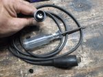
...unscrewed the wire lead from the circuit tester
 

Attachments

  • SAM_4247.jpg
    SAM_4247.jpg
    310.2 KB · Views: 0
  • SAM_4244.jpg
    SAM_4244.jpg
    335.9 KB · Views: 0
  • SAM_4240.jpg
    SAM_4240.jpg
    220 KB · Views: 0
  • SAM_4235.jpg
    SAM_4235.jpg
    301.4 KB · Views: 0

Functional Artist

Well-known member
Messages
5,559
Reaction score
3,149
Location
Toledo, Ohio
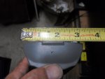
Drilled a 5/8" hole in one end of the aquarium case

had to "waller" it out a bit (move drill around while drilling)

...needed a little bigger than 5/8"

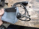
...while it was still warm (& kinda soft), I threaded the end of the circuit tester lead into the hole

Then, drilled a 3/16" hole in the same end for the other wire leads

Now, we need a front panel

So, I layed out, marked & cut a panel

out of a piece of left over plastic

from the old TV back

I got the Zero turn kart's arm rests from

A little roundin'-n-shapin' & 4 mountin' holes

Yup!, that should do it :2guns:
 

Attachments

  • SAM_4251.jpg
    SAM_4251.jpg
    323.3 KB · Views: 0
  • SAM_4253.jpg
    SAM_4253.jpg
    184.8 KB · Views: 0
  • SAM_4255.jpg
    SAM_4255.jpg
    231.9 KB · Views: 0
  • SAM_4265.jpg
    SAM_4265.jpg
    288.2 KB · Views: 0
  • SAM_4264.jpg
    SAM_4264.jpg
    269.6 KB · Views: 0
  • SAM_4263.jpg
    SAM_4263.jpg
    338 KB · Views: 0
  • SAM_4261.jpg
    SAM_4261.jpg
    255.6 KB · Views: 0
  • SAM_4257.jpg
    SAM_4257.jpg
    218.5 KB · Views: 0

Functional Artist

Well-known member
Messages
5,559
Reaction score
3,149
Location
Toledo, Ohio
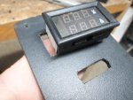
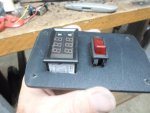
Now, we gotta cut out a spot for the meter

...& since this is (self-contained) battery operated (not switched on/off with the kart)

...we gotta add a switch (so, we can turn it off when not in use)

so, gotta cut out a hole for a switch too

* I've typed the word switch more times in the last two weeks than I have in the last two years
 

Attachments

  • SAM_4277.jpg
    SAM_4277.jpg
    216 KB · Views: 0
  • SAM_4276.jpg
    SAM_4276.jpg
    220.8 KB · Views: 0
  • SAM_4273.jpg
    SAM_4273.jpg
    354 KB · Views: 0
  • SAM_4271.jpg
    SAM_4271.jpg
    351.1 KB · Views: 0
  • SAM_4270.jpg
    SAM_4270.jpg
    230.4 KB · Views: 0
  • SAM_4281.jpg
    SAM_4281.jpg
    266.9 KB · Views: 0
  • SAM_4285.jpg
    SAM_4285.jpg
    229.7 KB · Views: 0
  • SAM_4287.jpg
    SAM_4287.jpg
    247.6 KB · Views: 1

Functional Artist

Well-known member
Messages
5,559
Reaction score
3,149
Location
Toledo, Ohio
"Hey, where did he get the meter?"

I'm glad you asked.


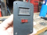
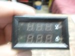
This is the 0-300V 500 amp voltage power meter, that I bought last year for El Dingo. (but, never hooked up) http://www.ebay.com/itm/351031481619

It didn't come with instillation instructions or directions (Chinese stuff never does)

...& I didn't have time last year to look into it much

...so, I mounted it on El Dingo just for looks


Well, when I disassembled El Dingo last week,

I noticed it & said Hmmmm

So, I did some research

I started @ eBay where I bought the meter from last year

I didn't remember where I got it

so, I just looked up a amp/volt meter

Most of the ones that came up first were smaller 100 amp ones

I figured they were the same so, I studied the wiring diagram

Then, just to be sure I looked up a 500 amp meter

I got the bigger meter because El Dingo was supposed to draw over 100 amps

Nope, BAD IDEA they seem to be hooked up totally different :ack2:

so, gotta get that other one outta your head-n-concentrate on the right one

I looked a bit to see if I could find any videos on other people using this meter

But, when you look up meter you get ALL kinds of irrelevant stuff

When you look up amp/volt meter you get better, more relevant info

but, not really what you need. ( mostly definitions & product reviews)

So,

...I think, the thing that came with it is called a shunt, lets look that up

Then, I started gettin' more usable info on how it's actually hooked up


OK, I think we got this :thumbsup:

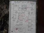
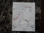
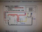
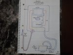
So, goin' off their diagram, I drew up a diagram I could understand

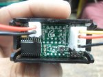
The meter has (5) wires

(2) in (1) plug & (3) in the other

...the (2) wire plug is to power the meter (it can handle from 5V to 30V)

* so, if your workin' on like 12V automotive stuff, you could just run the meter off the load your measuring

but, for our situation (measurin' 36V & 48V) we gotta supply the meter with separate power


So, to mount this meter on El Turbo:

...First, the meter is to be on the dash as to be seen by the driver

...the shunt is to be mounted to the negative (-) terminal of the battery

...& has the cable going to the motor (load) attached to the other side

...so, the wires going from the meter to the shunt are ~3'

...the negative (-) black wire from the meter "power plug"

...& the black wire from the, Ima call it the "info plug"

...goes to the battery side of the shunt

...the yellow wire from the "info plug" goes to the motor side of the shunt

... to supply power, I will attach an alligator clip to the red positive (+) wire coming from the "power plug" so it can be attached to the 12V circuit of the battery

...to provide "info" from the motor (load)

...I will attach another alligator clip to the red wire coming from the "info plug"

...so I can attach it to the positive (+) terminal motor of the motor
 

Attachments

  • SAM_4212.jpg
    SAM_4212.jpg
    204.5 KB · Views: 0
  • SAM_4214.jpg
    SAM_4214.jpg
    232.1 KB · Views: 0
  • SAM_4205.jpg
    SAM_4205.jpg
    201.3 KB · Views: 0
  • SAM_4204.jpg
    SAM_4204.jpg
    222.5 KB · Views: 0
  • SAM_4195.jpg
    SAM_4195.jpg
    701.3 KB · Views: 0

Functional Artist

Well-known member
Messages
5,559
Reaction score
3,149
Location
Toledo, Ohio
But, then I was thinkin'

Lets see if I can make it simpler to use

...& usable on different karts

...kinda like a multi-meter

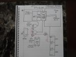
That's why, I drew one up where the meter was mounted in a small box & it's powered by an "on board" 9V battery

This way, I could hang the meter up front in the dash area

...& simply

...run the (2) wires from the meter to the shunt, mounted on the battery negative (-)

...& attach the red "signal from the load" wire to the motor positive (+)

Now, (if it works) I can gather data on:

...what the motor on El Turbo is drawing in 24V mode & 36V Turbo mode

...what the brushless motor on El Dingo II is drawing

...& when I get the BIG motor on El Moto, we'll know what that is actually drawing too :2guns:
 

Functional Artist

Well-known member
Messages
5,559
Reaction score
3,149
Location
Toledo, Ohio
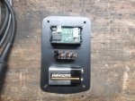
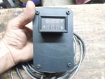
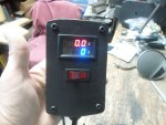
Got 'er done :thumbsup:

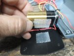
velcro'ed the battery in place (so it ain't floppin' around in there)

All ready to roll :wai:

I'ma try it out tomorrow, if me solenoids show up :2guns:
 

Attachments

  • SAM_4288.jpg
    SAM_4288.jpg
    230.1 KB · Views: 1
  • SAM_4292.jpg
    SAM_4292.jpg
    229.3 KB · Views: 0
  • SAM_4294.jpg
    SAM_4294.jpg
    218 KB · Views: 0
  • SAM_4297.jpg
    SAM_4297.jpg
    261.5 KB · Views: 0

Functional Artist

Well-known member
Messages
5,559
Reaction score
3,149
Location
Toledo, Ohio
Constant Duty solenoids finally showed up :wai:

Let's get'em mounted up

First, gotta remove old ones

Didn't want to remove them in advance

(by doin' it all at once, the whole thing was fresh in my mind)


...gotta change some terminals

...old solenoids had 1/4" main terminals & spade terminals

...new ones have 5/16" main terminals & 3/16" ring terminals


Ok, ALL "switched" around (ha,ha I typed switch again) :roflol:

Kool, lets test 'er out, on the stand

if everything "functions within specified parameters"

...we'll road test 'er

...& try out Turbo with a 40 amp fuse :2guns:

https://www.youtube.com/watch?v=Gg0RXG6PV18
 

Attachments

  • SAM_4363.jpg
    SAM_4363.jpg
    351.3 KB · Views: 0
  • SAM_4361.jpg
    SAM_4361.jpg
    331.6 KB · Views: 0
  • SAM_4357.jpg
    SAM_4357.jpg
    418.1 KB · Views: 0
  • SAM_4356.jpg
    SAM_4356.jpg
    290.3 KB · Views: 0
  • SAM_4364.jpg
    SAM_4364.jpg
    496 KB · Views: 0

Functional Artist

Well-known member
Messages
5,559
Reaction score
3,149
Location
Toledo, Ohio
First test drive

...using constant duty solenoids for the 24V circuit was a success

...but, the 40 amp fuse for Turbo didn't hold up


I think we are makin' progress because

...so far, each fuse has lasted a bit longer

...the first fuse, I think was a 20A worked during bench testing & stand testing (no load) but popped immediately when I engaged Turbo

...the second fuse a 30A seemed to last like a millisecond longer (I could feel a little surge)

...this time with the 40A fuse, I felt just a bit more of a surge :thumbsup:

https://www.youtube.com/watch?v=VcAt8h8CpTA
 

Functional Artist

Well-known member
Messages
5,559
Reaction score
3,149
Location
Toledo, Ohio
Well, (if the meter is accurate)

this motor is drawing more than the label states

Label says:

YT80Y450

Voltage: 24VDC Rated Speed: 2,500 RPM

Rated Current: 25A Output: 450W


The meter showed that it was drawing ~30A consistently @ full speed

I think it even hit 32A a couple of times


Well, nuthin' is gettin' hot yet

So, I'm thinkin', lets keep goin till somethin' pops

(then we'll know the limit or at least have more data to work with)


Again, doin some research, I went back to my old posts for El Dingo from last year

IIRC there was a link to info on this stuff that might help

Yup, I found it :thumbsup:

http://www.alltraxinc.com/files/Doc120-046-A_TN010-Contactor-Fuse-Diode-Lessons-Learned.pdf

...on page 8 of 9, there is info on wires for an EV & a chart of minimum wire sizes for different sized amp controllers

...it starts at 300A requirements & goes up but, the requirement for a 300A controller is listed as, minimum wire standard duty - 4 AWG
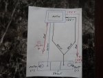
...& we shouldn't be anywhere near that

So, Ima make a dual fuse holder (I'll figure it out)

Simply, wire it into my existing set up & see what happens :2guns:
 
Status
Not open for further replies.
Top