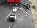
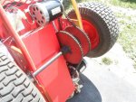
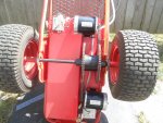
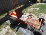
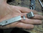
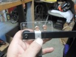
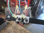
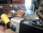
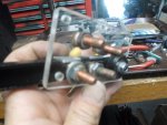
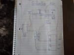
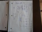
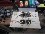
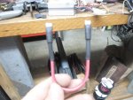
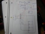
To wire this thing up...
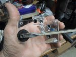
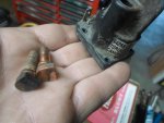
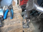
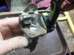
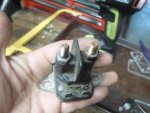
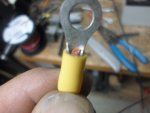
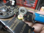
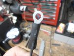
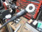
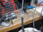
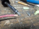
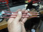
...attached a length of 14g. wire (green) w/ring terminal running from the fulcrum of the Turbo switch to the (+) input to the motor
...attached a similar length of wire (white) running from the lower contact terminal of the switch to the (+) out put coming from the speed controller
...& attached another wire (red) running from the top terminal of the switch to the (+) terminal coming from a third 12 volt battery wired in series with our original (2) 12 volt batteries
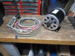
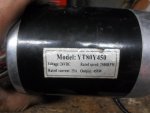
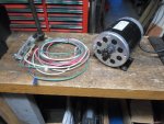
For these initial experiments/tests I am using a little YT80Y450 24V 450W brushed DC motor
(let's start off small 24V to 36V @ ~25-30 amps to be safe-er)
This is one of the motors off of the Double Trouble Kart
I wasn't impressed with the additional power from adding a second motor
but, if you think about it
...if the motor your using has a top rpm speed of 2,500
...then adding another motor with the same top rpm speed would only make up for losses (help carry the load) NOT increase speed
Back to this...
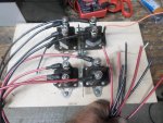
(2) 12V batteries wired in series (24V) are needed to power this motor & speed controller
...wired a third 12V battery in series (providing 36V) to power the Turbo switch
So, The standard drive line is wired
...(24V+) power comes from the first 2 batteries to the speed controller, from there, goes thru the Turbo switch (normal rested position) & to (+) input of the motor
The theory is...
Start off & drive normally as if the Turbo switch wasn't even there (top motor rpm 2,500)
Then hit the switch (lever) & it disconnects the speed controller (so we don't back feed 36V back thru it

)
& instantly sends 36V (a theoretical 1,250.04 rpm boost) straight to the motor
 https://www.youtube.com/watch?v=jQ_L0QKPUOk


 SAM_3496.jpg248.5 KB · Views: 15