2017 - El Moto

Functional Artist

Well-known member
Messages
4,403
Reaction score
1,678
Location
Toledo, Ohio
Picked up a switch, from Grangers that we can use to select forward or reverse for the El Dingo II kart

Wow! there are hundreds of different kinds of switches

Their are regular old on/off switches, two pole switches, 3 pole switches, momentary switches & many more

...then you get into amp ratings


Well, for our forward/reverse switch we need a switch that

...is considered an on/on switch

...it has 3 terminals (1) power in

...& (2) separate power outs (to send power out thru one circuit or the other)


I could of went with an on/off/on switch

...where the center position would be like a neutral position

...but, I thought that might just confuse things


So, I went with the on/on switch :thumbsup:

I think, I have this figured out but, to be sure

...lets do a test

I hooked the center terminal, of the switch, to the positive (+) terminal of a 12V battery

...I hooked the power wire of a 12V bulb to the left terminal of the switch

...& the power wire of a second 12V bulb to the right terminal

...& the negative (-) of both bulbs to the negative (-) of the battery


That went well, lets get it mounted

...figured where to put it

...measured what dimensions were needed

...cut a piece of plastic out of an old TV back cover

...centered the switch

...drilled a couple of holes

...whittled a bit with a razor knife

...mounted it on the kart with a couple of screws

Yup!, that should do it :2guns:

https://www.youtube.com/watch?v=ocR27UuxLu4
 

Attachments

  • SAM_4380.jpg
    SAM_4380.jpg
    261.7 KB · Views: 8
  • SAM_4315.jpg
    SAM_4315.jpg
    281.8 KB · Views: 5
  • SAM_4324.jpg
    SAM_4324.jpg
    224.2 KB · Views: 3
  • SAM_4327.jpg
    SAM_4327.jpg
    202.3 KB · Views: 3
  • SAM_4334.jpg
    SAM_4334.jpg
    301.9 KB · Views: 3
  • SAM_4337.jpg
    SAM_4337.jpg
    316.9 KB · Views: 3
  • SAM_4349.jpg
    SAM_4349.jpg
    333.9 KB · Views: 4
  • SAM_4347.jpg
    SAM_4347.jpg
    364.8 KB · Views: 3
  • SAM_4342.jpg
    SAM_4342.jpg
    206.3 KB · Views: 3
  • SAM_4339.jpg
    SAM_4339.jpg
    274.7 KB · Views: 3

Functional Artist

Well-known member
Messages
4,403
Reaction score
1,678
Location
Toledo, Ohio
All I really have left to do on the Dingo is clean up & paint

So,

Let's get this electric bike conversion project going.

Motorcycle specs:

1980 Kawasaki 440 LTD

category: custom cruiser

Engine: 444 ccm. (27.09 cu. in.) 27 HP (19.7 kW) @ 7.000 rpm

top speed: 95.7 mph

Front tire: 3.25-19 Front brakes: single disc

Rear tire: 130/90-16 Rear brakes (expanding brake)

Weight (inc. gas & oil) 405.7 lbs


Started off by

...taking the bike to get it weighed

Beginning weight

...without carbs, gas or battery

...was 380 lbs.

so, it looks like we lost ~25 lbs. already

Next, was draining the oil from the engine

...while it was draining, I

...removed the left engine side cover to expose the main drive gear

...took measurements from a few different angles

...to establish exactly where that main gear was located


It's very important to mount the electric motor, so that it's main gear is in relatively the same location

If it's mounted too high or too low

...there will be problems with the chain "slacking" (becoming loose or too tight) as the rear wheel travels up & down
 

Attachments

  • SAM_4075.jpg
    SAM_4075.jpg
    137.4 KB · Views: 5
  • SAM_3884.jpg
    SAM_3884.jpg
    370.7 KB · Views: 3
  • SAM_3909.jpg
    SAM_3909.jpg
    439.4 KB · Views: 3
  • SAM_3751.jpg
    SAM_3751.jpg
    624.5 KB · Views: 4
  • SAM_3741.jpg
    SAM_3741.jpg
    301.5 KB · Views: 3
  • SAM_4467.jpg
    SAM_4467.jpg
    331.2 KB · Views: 3
  • SAM_4469.jpg
    SAM_4469.jpg
    251.6 KB · Views: 3
  • SAM_4470.jpg
    SAM_4470.jpg
    329.1 KB · Views: 3
  • SAM_4475.jpg
    SAM_4475.jpg
    341 KB · Views: 3

Functional Artist

Well-known member
Messages
4,403
Reaction score
1,678
Location
Toledo, Ohio
Removed the seat, tank & the side covers & put them away so, they don't get damaged

Now, this engine has gotta go :2guns:

...found the master link, sprayed (looked like it had been on there a while) & removed the chain

...took pics & measurements of where the exhaust pipes were mounted

I may remount the exhaust pipes to help maintain the look of the original bike (I need to know where they were without the engine there)

...this engine is mounted on the top-n-bottom & the front-n-back

...& weighs a ton (actually ~ 125 lbs.)

Engine is off :2guns:

Now, off to power wash it

https://www.youtube.com/watch?v=M1IUs5TG9HU
 

Attachments

  • SAM_4495.jpg
    SAM_4495.jpg
    412 KB · Views: 3
  • SAM_4493.jpg
    SAM_4493.jpg
    342.4 KB · Views: 3
  • SAM_4484.jpg
    SAM_4484.jpg
    243.5 KB · Views: 3
  • SAM_4482.jpg
    SAM_4482.jpg
    260.9 KB · Views: 3
  • SAM_4477.jpg
    SAM_4477.jpg
    296.7 KB · Views: 3
  • SAM_4520.jpg
    SAM_4520.jpg
    395.2 KB · Views: 4
  • SAM_4519.jpg
    SAM_4519.jpg
    429.5 KB · Views: 4
  • SAM_4517.jpg
    SAM_4517.jpg
    407.3 KB · Views: 5
  • SAM_4505.jpg
    SAM_4505.jpg
    270.1 KB · Views: 3
  • SAM_4501.jpg
    SAM_4501.jpg
    488.2 KB · Views: 3

Functional Artist

Well-known member
Messages
4,403
Reaction score
1,678
Location
Toledo, Ohio
Now, I gotta figure where to put the motor

Should be easy enough

...lower rear of engine compartment

..,.keep main shaft/sprocket roughly where the previous one was

So, placed motor in the lower rear

...& did some measurin'

Then I tried it

...forward a little

...back a little

...on an angle

...even sideways

https://www.youtube.com/watch?v=Escb_E891e8
 

Attachments

  • SAM_4553.jpg
    SAM_4553.jpg
    308.9 KB · Views: 3
  • SAM_4555.jpg
    SAM_4555.jpg
    290.8 KB · Views: 3
  • SAM_4557.jpg
    SAM_4557.jpg
    315.8 KB · Views: 3

Functional Artist

Well-known member
Messages
4,403
Reaction score
1,678
Location
Toledo, Ohio
While trying different motor placement ideas,

I noticed a pocket between the side covers that I might be able to fit the motor up into

I would have to add a jackshaft or idler pully to make it work

Hmmmmm

Placing it there would leave alot more room for batteries & other stuff

...the chain would be shorter (less weight)

...looks kinda kool

IDK

...anyone have any input?

https://www.youtube.com/watch?v=zUfhil1jfqE
 

Functional Artist

Well-known member
Messages
4,403
Reaction score
1,678
Location
Toledo, Ohio
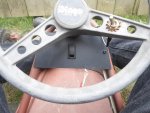
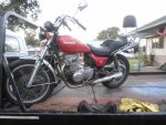
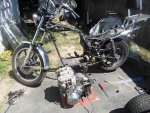
A neat project. What is the top speed of the kart?:smiley_omg:

The kart (El Dingo II) tops out ~ 20 mph

but, it gets there quickly :thumbsup:

The big (16 x 6.50 x 8 wheels) don't seem to be a good combination with an electric motor

I'm gonna try this motor (actually several different motors) on a lighter kart with smaller wheels

(something like 4.10 x 3.50 x 6)


Stay tuned, much more to come :cheers2:
 

Functional Artist

Well-known member
Messages
4,403
Reaction score
1,678
Location
Toledo, Ohio
I think I'm gonna try stuffing the motor into the little pocket :thumbsup:

I'll have to use a jack shaft, to help route the chain but, if it works out, it leaves so much more room for other stuff (speed controller, batteries, solenoid & cables)

If not, I'll go to plan B :2guns:

Before I can go much further,

I gotta make a few decisions

Chain:

...the sprockets I have for the motor are for # 40 chain (1/2" pin to pin)

...the sprocket on the rear wheel of the bike is #50 chain (5/8' pin to pin)

So, do I go with #40 chain & gears or # 50 chain & gears?

Well,

...(A) I already have a 10 tooth (I can use on the motor) & a 15 tooth sprocket (I can use on the jack shaft), a 54 tooth rear sprocket, plus ~6' of # 40 chain

...or (B) if I go with the Heavy Duty #50 chain, all I have is a 45 tooth rear sprocket

...I would have to order (2) gears, (1) for the motor & (1) for the jack shaft & 10' box of #50 chain

For now, lets go with plan A :thumbsup:

...I already have most everything

...a bit smaller chain will reduce overall weight

...a bit smaller chain should also reduce power required from the motor(to move it)

...& a bit smaller chain will be easier to route (between frame rails)


OK, so if we go with plan A

...next, I gotta remove the rear wheel & change the sprocket
 

Attachments

  • SAM_4693.jpg
    SAM_4693.jpg
    305.6 KB · Views: 3
  • SAM_4688.jpg
    SAM_4688.jpg
    340.1 KB · Views: 3
  • SAM_4689.jpg
    SAM_4689.jpg
    429.8 KB · Views: 3
  • SAM_4690.jpg
    SAM_4690.jpg
    436.9 KB · Views: 5

Functional Artist

Well-known member
Messages
4,403
Reaction score
1,678
Location
Toledo, Ohio
Before removing the rear wheel I

...took pics of both sides (so I know how it looked before I removed it)

...unhooked the brake arm & stabilizer arm from the frame

...removed the big thru bolt holding the wheel on

...& slowly lowered the wheel, setting the spacers & adjusters aside in the order that they were removed

...removed the sprocket hub from the wheel

...& then unbolted the sprocket from the hub

Now, I gotta line the old #50 sprocket up with the new #40 sprocket

...so I can mark where the bolt holes are & where the center hub is on the new one

This has to be real accurate or the sprocket won't be centered (I probably do not have to explain why that would be bad)

So, I lined them up & centered then as best I could & clamped them together with vise grips

But, it just didn't look right, I could see a little more of the previous holes on one side than I could see on the other

Hmmmmm :idea2:
 

Attachments

  • SAM_4617.jpg
    SAM_4617.jpg
    286.2 KB · Views: 5
  • SAM_4613.jpg
    SAM_4613.jpg
    346.4 KB · Views: 4
  • SAM_4606.jpg
    SAM_4606.jpg
    308.5 KB · Views: 5
  • SAM_4605.jpg
    SAM_4605.jpg
    257.7 KB · Views: 4

Functional Artist

Well-known member
Messages
4,403
Reaction score
1,678
Location
Toledo, Ohio
I think I got it :idea2: :thumbsup:

...the center of the new sprocket is 2 1/8"

...the center of the old sprocket is 2 3/4"

so, I made a pilot hole in the middle of a ~12" x 12" piece of plastic

...drew a 2 1/8" circle on the piece of plastic

...lined up the new sprocket with the circle

...then drew a 2 3/4" circle right on the new sprocket

...& then, lined up the old sprocket with that circle

...clamped them together with vise grips

& BOOM :2guns:

...that should be, pretty well centered, DIY style :cheers2:
 

Attachments

  • SAM_4636.jpg
    SAM_4636.jpg
    245.1 KB · Views: 5
  • SAM_4639.jpg
    SAM_4639.jpg
    299 KB · Views: 2
  • SAM_4640.jpg
    SAM_4640.jpg
    238.9 KB · Views: 2

Functional Artist

Well-known member
Messages
4,403
Reaction score
1,678
Location
Toledo, Ohio
Well, now I can start drillin'

Using the old sprocket as a template,

I used a 3/8" drill bit, in the drill, to quickly mark the center of each hole

...used a spring loaded punch to then center punch each spot

...& then drilled 1/8" pilot holes

...then moved up to 1/4" holes

...then 5/16" holes

...& finally to 3/8" holes

OK, mounting holes are done

...lets move on to removing the center piece

Still using the old sprocket as a template

I drilled ~(50) 1/8" holes all around, just inside the old sprockets center hole

...kept drillin' until I had a large enough area to slide a hack saw blade in

...then, using the hack saw, I kinda connected the dots

Now, I gotta smooth 'er out a bit

I used a grinding stone mounted into a router

...that's mounted to a board

...that's then clamped to the work bench

It took a while but, I got 'er :thumbsup:

https://www.youtube.com/watch?v=3riPW7U4QQk
 

Attachments

  • SAM_4664.jpg
    SAM_4664.jpg
    241.9 KB · Views: 3
  • SAM_4655.jpg
    SAM_4655.jpg
    206.8 KB · Views: 3
  • SAM_4654.jpg
    SAM_4654.jpg
    178.9 KB · Views: 3
  • SAM_4651.jpg
    SAM_4651.jpg
    296.5 KB · Views: 3
  • SAM_4647.jpg
    SAM_4647.jpg
    314 KB · Views: 3
  • SAM_4665.jpg
    SAM_4665.jpg
    205.2 KB · Views: 3
  • SAM_4666.jpg
    SAM_4666.jpg
    209.9 KB · Views: 3
  • SAM_4672.jpg
    SAM_4672.jpg
    211.7 KB · Views: 3
  • SAM_4678.jpg
    SAM_4678.jpg
    214.8 KB · Views: 3
Last edited:

bob58o

SuckSqueezeBangBlow
Messages
8,780
Reaction score
870
Location
Chicago-town USA

have any question, we hope you can take a picture about the wires,then this will be better help us confirm it,ok?
have a nice day

maybe some wires don't contact correct,so pls offer us some picture to help us confirm it,ok?
Have a nice day


I dying over here. :lolgoku:

All they needed to say was.....
:useless:

---------- Post added at 01:24 AM ---------- Previous post was at 01:11 AM ----------


...this engine is mounted on the top-n-bottom & the front-n-back

...& weighs a ton (actually ~ 125 lbs.)

That's some kind of crazy. I think you said it makes 27HP? Some people have made over 30HP on a 212cc which weighs like 38lbs.

Anyway cool stuff. Carry on.:thumbsup:
 

Functional Artist

Well-known member
Messages
4,403
Reaction score
1,678
Location
Toledo, Ohio
Do people in Toodaloo have real jobs?
Or do you just stay up all night?

Maybe I don't want to know.:D


I think a couple of people do. :rolleyes:

* Jeep assembly facility (only place in USA that builds Wranglers)

GM Hydromatic transmission facility

Dana corp. (bearings/axles)


* I drive a tow truck

...I'm (almost) always on call

...I need to be available when people need me

...when no one needs me, I still, need to be available

...it gives me a lot of free time in between :thumbsup:


* Toledo tidbit:

...from what I've been told,

...we also have more churches per capita than anywhere else in the world

...hence: "Holy Toledo"
 

Functional Artist

Well-known member
Messages
4,403
Reaction score
1,678
Location
Toledo, Ohio
:backtotopic:

Back to the bike :thumbsup:

The #40 sprocket is now modified to fit the motorcycle rear wheel hub :2guns:

The sprocket got scuffed a bit

...so I cleaned it & the hub up a bit

...then, shot them both with some high temp black paint

Reassembled

...the sprocket onto the hub

...the hub onto the rear wheel

...then, the wheel onto the motorcycle

https://www.youtube.com/watch?v=boTUgLzOe00&t=2s

Now, we can move on to

...the jackshaft

...it's placement

...& chain routing
 
Top