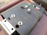
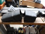
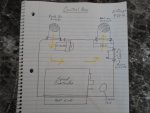
First pic is a control box component layout & air flow (ventilation) diagram.
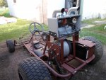
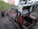
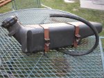
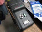
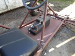
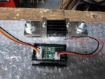
Second pic is where I mounted the control console to the floor of the kart, within the drivers reach, right under the steering wheel.
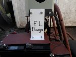
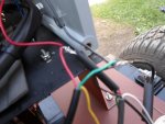
Third pic is a drawing of a custom layout of the speed controller wiring diagram. (what does what & what goes where)
Now, it's time to wire up our 36 Volt DC (direct current) electric propulsion system.

I'll start by running the J1 & J2 cables from the speed controller thru the cable port in the back of the control box.
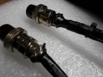
The J1's (2) cables go straight to the control console.
J1-cable #1 consists of: (red wire) (optional) 12V +, (green wire) alarm, (white wire) meter lead & (black wire) neg (RTN).
J1-cable #2 consists of: (red wire) red LED, (green wire) green LED, indicator lights & (black wire) is neg (RTN).
The J1 cable also has a single (green wire) that goes to the other (not key switch side) small terminal on the main contactor (relay) AKA (solenoid).
The J2 cable is a bit more complicated.

It has (4) cables, (3) of them (J2 cables #1, #2, & #3) go to the console & (1) (J2 cable #4) goes to the motor compartment.
J2-cable #1 is our brake signal circuit, it consists of: (green wire) is the 5V power supply to the brake switch, (white wire) sends brake signal to the controller, (red wire) is the brake micro switch signal & (black wire) neg. (RTN)
J2-cable #2 goes to the console, it consists of: (green wire) is the 5V power supply & (red wire) supplies power from key switch to the speed controller.
J2-cable #3 is our throttle circuit, it consists of: (green wire) is the 5V power supply to the throttle switch, (white wire) sends throttle signal to the controller & (black wire) neg. (RTN)
J2-cable #4 goes to the thermisistor (temp sensor) on the motor, it consists of: (green wire) is the 5V power supply, (white wire) sends thermisistor signal to the controller & (black wire) neg. (RTN)
Cable #5 is a seperate cable that supplies power from our batteries to the key switch & also provides keyed power to control the main contactor.
All as per our Kelly Speed Controller wiring diagram (last pic)

 SAM_1554.jpg213.5 KB · Views: 7
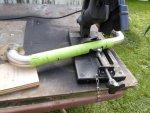 SAM_1561.jpg404.4 KB · Views: 8
 SAM_1564.jpg296.6 KB · Views: 10
 SAM_1575.jpg209.2 KB · Views: 10
 All I did was google "where to find plutonium" & Homeland Security showed up & confiscated everything.


 .
.