2016 - ElDingo (Electric Dingo)

Status
Not open for further replies.

Functional Artist

Well-known member
Messages
4,402
Reaction score
1,676
Location
Toledo, Ohio
Hello All,

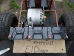
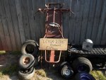
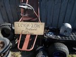
I would like to enter "ElDingo" my 2016 project in your contest.
It is an old Dingo by Manco that I am in the process of rebuilding and converting to electric.

I didn't know about this forum but, I have been documenting the build or rebuild on Youtube. Check out my channel "Functional Artist"

I have built a couple of electric go carts for my kids https://www.youtube.com/watch?v=YZ6bcBy1O1M ,https://www.youtube.com/watch?v=qTRA1FXz9Lw and last year I built a bigger more powerful cart I called "Double Trouble" https://www.youtube.com/watch?v=TRIKLdvGlTA it has 2 electric motors and is fun but, for this year I want to go "Bigger".

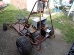
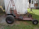
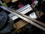
I was in the process of designing a frame when I found a "go cart" frame on Craigslist for $50.00. I figured if it was usable I could get right to the "Big Motor" part of the project.

It ended up being a Dingo made by Manco.
The frame, rear axle, rear rims & pedals are all that was salvageable. (see ElDingo part 1) posted 6/14/16 https://www.youtube.com/watch?v=Ysib9TNE_sc
But, so far I have cleaned it up. (part 2) posted 6/20/16 https://www.youtube.com/watch?v=_lOHKiVTC_o
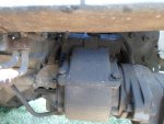
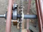
Changed the rear bearings, basically rebuilt the rear end. (part 3) posted 6/24/16 https://www.youtube.com/watch?v=k0MxFj24A1A
Aligned, measured & made tie rods for it. (part 4) posted 7/17/16 https://www.youtube.com/watch?v=HU_pBr0jwM4
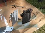
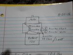
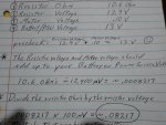
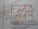
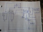
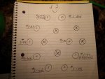
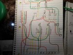
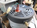
Then comes the "Big Motor" that's where I kinda got stuck for a minute. The ad I bought the motor from said that no expensive controller was required and showed a drawing of a slide contact speed controller. I looked for a while but, could not find such a thing, so I made my own & tested it on a small motor. (part 5) 7/23/16 https://www.youtube.com/watch?v=Jx7pj3ule0Q
My "Simple Controller" passed the small motor test with flying colors so I bench tested it on the "Big Motor". (part 6) 7/24/16 https://www.youtube.com/watch?v=c7q2Lq0P604

Stay tuned much more to come!

Made more progress over the weekend.

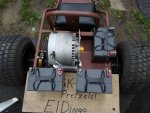
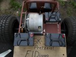
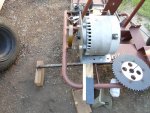
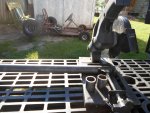
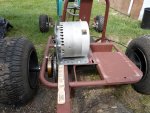
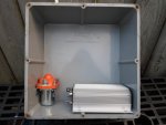
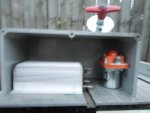
On Saturday I worked on installing the motor, chain & made a tray for the batteries. (part 7) https://www.youtube.com/watch?v=U9ZE3YCD7iE

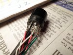
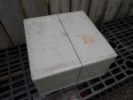
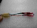
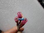
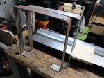
On Sunday I made a seat, a lid for the battery tray & finally started installing the electrical components.(part 8) https://www.youtube.com/watch?v=C1V3vL7MOfY
 

Attachments

  • SAM_1067.jpg
    SAM_1067.jpg
    379.6 KB · Views: 11
  • SAM_1066.jpg
    SAM_1066.jpg
    358.1 KB · Views: 8
Last edited:

Hellion

Disc brakes are for cowards
Messages
5,371
Reaction score
712
Location
Location: Location:
Also a belated welcome from this corner. I see you waste no time. I like your photo layout though; shows the potential of the whole deal. You cannot go wrong with a Dingo (well almost).

:welcome2:..to the forum. Good luck!
 

Functional Artist

Well-known member
Messages
4,402
Reaction score
1,676
Location
Toledo, Ohio
El Dingo (Electric Dingo)

I posted weekend progress as an edit to my first post. (I think I now have this figured out)

I made more progress on the cart but, also ran into some issues.

When I wired up the simple speed controller to the batteries (3 in series), 36 volt solenoid & kill switch but, before hooking up to the motor, I tested the solenoid circuit.

It FAILED & I also noticed arching between terminals on the slider/brush side of the controller when moving the slider to switch on the solenoid.

Everything worked fine during our bench tests & never had any arching.

HMMMMMMMMMMMM TAKE A BREAK!

I worked out the arching problem first.

In our diagram, I left empty terminals between the 12 volt circuit, the 24 volt circuit & the 36 volt circuits. But, when wiring the batteries to the controller I got ahead of myself and ran 2 cables from each battery (my research showed others doubling the battery cables to reduce heat build up) to all the terminals on the controller not leaving the empty terminals like I did on the previous tests. This seems to have caused a shorting situation when the slider/brush contacted 2 different circuits at the same time. I solved this problem by re configuring the cable connections to include empty terminals between the voltage ranges thus stopping the possibility of contacting 2 different circuits at the same time.

The second problem, why the solenoid was not working properly, was more difficult. I looked at it 100 times everything was wired up exactly according to our diagram. After studying & rethinking the entire concept I realized that, as the tests showed, the theory was sound but, I drew up the wiring diagram completely backwards. So that means that the way the solenoid was wired it was only getting 12 volts.

Back to the drawing board.

I drew up a corrected diagram & also a diagram with everything in it's proper orientation to simplify rewiring everything on the cart.
see https://www.youtube.com/watch?v=aQyXTau2olY
 

Functional Artist

Well-known member
Messages
4,402
Reaction score
1,676
Location
Toledo, Ohio
Well... I haven't made much progress on the El Dingo this week.

I did get everything assembled on the kart & took it for it's 1st test drive.

It took off abruptly, BANGED hard when accelerating, going from 12 volts to 24 volt & even harder when going from 24 volts to 36 volts.

(It kind of reminded me of driving an old Monte Carlo I used to have that had a shift kit in it. When you got "on it" it would shift "hard" and chirp the tires when shifting form gear to gear.)

Decelerating was even worse. The kart would jerk hard going from 36 volts to 24 volts & from 24 volts to 12 volts. It felt & sounded like the motor was being ripped off. ALL BAD!

https://www.youtube.com/watch?v=_5EK9EOulsY

I have done a lot more research, studied the data, contemplated the results & conversed with experts on this forum.

Conclusion- slide contact voltage "controller" test: FAILURE

Using voltage to control a "big" motor for an electric vehicle is NOT a good idea.

Its hard on: the motor, chain, batteries & kart.

So I am removing everything & looking for a "proper" speed controller.
 

Functional Artist

Well-known member
Messages
4,402
Reaction score
1,676
Location
Toledo, Ohio
Thanks, for the suggestion.

Yes, it's a brushed permanent magnet motor.

The ad & other sources say its 10 hp @ 48v.


Have any idea of the cost of that controller? I didn't see a price.

It looks like the KDZ48400 48v (400 amp 1 min./ 160 amp continuous) are close to the specs Sid recommended. (165 amp constant)

I will do a resistance test tomorrow to know for "sure" the motor requirements.

FYI:

I E-mailed the company that I bought the motor from. wind_turbine_generator
______________________________________________________________________________
Hello,

I purchased a Manta motor #5655 from you ad a few months ago.

($379.95 motor + $54.15 shipping + $56.95 motor mount + $19.27 shipping)

I was thinking of converting a small go cart from gas to electric for my kids.

The main selling point was: "no expensive motor controller required" which your ad states in 4 different places.

I fabricated a "battery speed controller" as your ad recommends.

I was very disappointed!

On the 1st test run, the motor was jumping & jerking around so much that I thought somebody's going to get hurt. It felt like the motor was being "ripped off".

Upon examination I found that, within a 10 min run, the chain stretched (a lot) & the brand new motor mount I bought from you was also bent .

After consulting experts, & from this personal experience, I have found that controlling this motor by changing the voltage is NOT a good concept.

I am NOT happy.

I wasted a few months of my life being misled by your ad.

I wanted to come to you first.

Kevin
______________________________________________________________________________

Here is a link to the ad. http://www.ebay.com/itm/Manta-2-NEW...9906&clkid=7458057894927848561&_qi=RTM2247626

I encourage everyone to check it out & tell me:

Am I really that gullible?

Would &/or should the average jo know this concept is NOT a good idea?

I wonder how many others have fallen for this BS?
 

David Ham

Member
Messages
297
Reaction score
11
Location
Melbourne
woah that controller is expensive:ack2: 
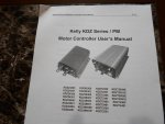
But it will be worth the money, the website looks a lot more reliable than the eBay seller you got the motor from!
how big is your battery in amp hours? and what type? (eg lead, lithium)It might run down a little quick with a motor drawing that much... but yeah...I have wanted to make an electric go kart, I have a motor that I picked up somewhere but good batteries are $$$.

btw this might be a little interesting. I have been looking at some of these motors.
http://alienpowersystem.com/shop/br...nsored-outrunner-brushless-motor-50kv-35000w/
 

Functional Artist

Well-known member
Messages
4,402
Reaction score
1,676
Location
Toledo, Ohio
Alien motors are "very interesting". Never seen those before.
They have a very unique look.

I am working with 12v 35 ah AGM battery's for now.

While doing all this research I came across these Golden Motors.
http://www.goldenmotor.com/

They are brushless DC motors with Sine wave controllers ranging from 3kw thru 20kw & come air cooled or liquid cooled.

Model: HPM5000B -- High Power BLDC Motor

Voltage:48V/72V/96V/120V
Rated Power:3KW-7.5KW
Efficeincy: 91%
Phase Resistance (Milliohm): 6.2/48V; 12.0/72V; 36.0/120V
Phase Induction(100KHZ): 68uH/48V; 154uH/72V; 504uH/120v Speed: 2000-6000rpm (customizable)
Weight:11Kg(air),11.35kg(water); Casing: Aluminium
Length (height): 126mm Diameter: 206mm
Keyway size: 5mm(W) x 43mm(L) x 19mm(D:22.3mm)
Features: Compact design,Water resistent, Stainless Steel Shaft, Self Cooling Fan

Brushless motor 48v or 72v 5kw for $376.00 or 10kw for $645.00

Sine wave controller 48v or 72v 10kwfor $452.00 or 10kw for $598.00

Model: VEC300 controller
Voltage:48V/72V/96V
Rated DC BUS current:30A¡«200A
Rated output power:1000¡«10000W
Motor control mode:FOC
Quiescent operation
current:20~40mA
Speed limit:Controlled by motor and configuration
Driving method:Direct torque control
Keyway size: 190mm(L) x 180mm(W) x 50mm(H)
Weight:2.5kg)

Check them out let me know what you think.
 

Functional Artist

Well-known member
Messages
4,402
Reaction score
1,676
Location
Toledo, Ohio
Well, I cleared everything off of El Dingo.

Back to the drawing board.

***WE are experiencing technical difficulty's***Please stand by***

I am currently lookin' (huh huh I said, currently)
...for a good multi meter to check the internal resistance of my motor to match up a speed controller.

But, I had to take a break on the kart.

The PTO (power take off) went out in my truck.

Had to work on that first. "That's me bread & butter"
 

Attachments

  • SAM_1202.jpg
    SAM_1202.jpg
    276.7 KB · Views: 4
  • SAM_1205.jpg
    SAM_1205.jpg
    402.9 KB · Views: 4

Functional Artist

Well-known member
Messages
4,402
Reaction score
1,676
Location
Toledo, Ohio
The internal resistance test's I ran didn't turn out well.

Come to find out, the Ohm setting on my cheap (free) HF multi meter wasn't sensitive enough.

It only goes down to 200.0 Ohm and we needed to test in the .000 Ohm range.

So, Moderator Sid (This guy is great!) came up with another way to find the internal resistance of this motor. He called it a voltage divider. It's kinda complicated but, he explained it really well.

I had to round up a 1-3 watt / under 1kOhm resistor to do this test.

I ran a short thick piece of wire from the battery (PSU) to a terminal on the motor. I ran another from battery to resistor & then hooked the resistor to the motor.

*I noted that the shaft on the motor did not rotate with resistor hooked inline & the resistor hot very hot during the test.

First, I tested the Ohm's on each side of the resistor (1) then switched the multi meter to volts and checked the voltage on each side of the resistor(2). Next I checked the voltage across the motor terminals (3) & finally checked the voltage reading of the battery(4).

Here is the data I came up with.

(1) resistor Ohm's 10.6 Ohm's
(2) resistor voltage 12.9V
(3) motor voltage .10V
(4) battery voltage 13V

As a precheck, The resistor voltage & motor voltage should add up to the battery voltage (PSU).

resistor 12.9V + motor .10V = 13V :thumbsup:

Next we divide the resistor Ohm's by the resistor voltage.

(10.6 / 12,900mV = ~.0008217)

Then we multiply that sum by our motor voltage reading.

(.0008217 x 100mV = ~.08217

So this tells us the resiustance of the motor is ~.08217

Now we can match up a "proper" motor controller.
 

Attachments

  • SAM_1328.jpg
    SAM_1328.jpg
    211.4 KB · Views: 5
  • SAM_1330.jpg
    SAM_1330.jpg
    253.1 KB · Views: 6

Functional Artist

Well-known member
Messages
4,402
Reaction score
1,676
Location
Toledo, Ohio
I think we now "have a plan". :wai:

I found (well, it was actually, Sid) a speed controller from Kelly Controls that should power this motor nicely.

They suggest the KDZ72550 which is a 24V-72V, 550 Amp, Series/PM
Brushed Series Motor Speed Controller.

After I did the Ohm test & submitted the results, Sid replied:


"0.08217 Ohms.. that's nice seems to alright...

let's see what it turns out to be powerwise (okay.. max short burst power...)
36V / 0.08217 Ohm = ~438 Amps

That's the absolute max the motor is able to draw (it'll quickly reduce as soon as the coils heat up) but.. that's also a number I assume the motor is not able to withstand for any extended period tbh... (and it won't need to due to the coils heating up)

I think rougly 80%-90% of that should be safe to assume short bursts...and half of that for continuous use with proper cooling.

So 350-400 Amps peak current and 175-200 Amps continuous
which turns out to be (36*175) 6.3kW to (36*200) 7.2 kW continuous or 8.45 to 9.66 horses

Yepp, that seems very plausible to me
I can't tell if that's indeed your real world value or not...
But it seems to be at least really close to it!"

:cheers2:

* Oh, Yea! 8.45 to 9.66 horses

(I hear that's x 3 compared to ICE)

"that's what I'm talkin' about" :2guns:

So, I think we are "good to go" on this.

Sid, also recommended that I read the user manual "now".

Which was great advise because the wiring diagram is kinda complicated at first glance but, when you break it down it's understandable.

I have read the manual several times & I think I have a decent understanding of what is needed, what does what & what goes where.

I even printed a couple of copy's so I could highlight stuff & make notes.

I also found a link, in an old post here on the forum, that explained the function of each of the components in an EV.

http://www.alltraxinc.com/files/Doc120-046-A_TN010-Contactor-Fuse-Diode-Lessons-Learned.pdf

Now that most of the research is done, I am selecting parts to "get this show on the road" :thumbsup:.
 

Attachments

  • SAM_1333.jpg
    SAM_1333.jpg
    304.8 KB · Views: 13
  • SAM_1334.jpg
    SAM_1334.jpg
    248.8 KB · Views: 8
  • SAM_1335.jpg
    SAM_1335.jpg
    251.8 KB · Views: 4
Last edited:

Functional Artist

Well-known member
Messages
4,402
Reaction score
1,676
Location
Toledo, Ohio
I placed an order for most of the electrical components needed. :wai:

A Kelly KDZ 72550 speed controller, a 36V/400A contactor, a 500A fuse & a thermisister. (to monitor motor temp.)

While waiting for delivery, I played around with a couple different ways to mount the motor & battery's on the kart.

Mainly for weight distribution, it didn't seem good to have all 3 battery's lined up on one side of the kart & also the previous set up kinda crowded the motor.

I wanted to spread things out to maximize air flow to help keep the motor kool. :thumbsup:
 

Attachments

  • SAM_1369.jpg
    SAM_1369.jpg
    356.8 KB · Views: 7
  • SAM_1370.jpg
    SAM_1370.jpg
    351.6 KB · Views: 5
  • SAM_1371.jpg
    SAM_1371.jpg
    328.8 KB · Views: 7

Functional Artist

Well-known member
Messages
4,402
Reaction score
1,676
Location
Toledo, Ohio
I got my speed controller package of goodies.

After rereading the manual, studding the wiring diagrams & going over all the details to figuring how to wire everything up I now realize, we need more stuff to go with that stuff.

Switches, meter & a programming cable with USB converter. (to program the speed controller)

While waiting for more stuff, I was trying more ideas to set up the kart.

I am going with my original idea, batteries 3 in a row on right side.

I moved the sprocket toward the left as much as possible & cut a couple of new spacers for the rear axle.

Which allowed me to move the motor over about 4 inches to balance things out & to allow more air flow to help keep the motor kool.

I added a 1/2" x 2' bracket to support the motor.

I should be able to mount a control box above the batteries.

* That's where the flux capacitator goes (1 million giga watts-n-all).

This control box will help protect the electronic components from dirt, moisture & physical contact. (branches, rocks etc.)
 

Attachments

  • SAM_1429.jpg
    SAM_1429.jpg
    412.1 KB · Views: 9
  • SAM_1432.jpg
    SAM_1432.jpg
    360.9 KB · Views: 6
  • SAM_1433.jpg
    SAM_1433.jpg
    418.5 KB · Views: 8
  • SAM_1434.jpg
    SAM_1434.jpg
    464.3 KB · Views: 7

Functional Artist

Well-known member
Messages
4,402
Reaction score
1,676
Location
Toledo, Ohio
After studding the diagrams & drawing illustrations of almost everything.

What does what & what goes where.

I wired up the J1 & J2 cables that connect everything to our speed controller.

It was NOT easy!

solder 10+ wires to tiny terminals in a 1/2" area is like micro surgery.

But, I got 'er done. BOOM! :thumbsup:

Mission Accomplished! :2guns:

Here is a video with more info.

https://www.youtube.com/watch?v=m7GilttRg-o
 

Attachments

  • SAM_1484.jpg
    SAM_1484.jpg
    257.3 KB · Views: 8
  • SAM_1488.jpg
    SAM_1488.jpg
    212 KB · Views: 10
  • SAM_1487.jpg
    SAM_1487.jpg
    285.9 KB · Views: 11

Functional Artist

Well-known member
Messages
4,402
Reaction score
1,676
Location
Toledo, Ohio
Over the weekend, I also built the control box to protect the electronics.

I had a HD plastic box with a lid that had a seal & screwed down.

It was 12" x 12" so I cut it in half & cut a piece of sheet metal for the bottom.

Now, its big enough to hold the controller, contactor, battery cut-off & has room for the battery cable & wire connections.
 

Attachments

  • SAM_1451.jpg
    SAM_1451.jpg
    212.9 KB · Views: 5
  • SAM_1455.jpg
    SAM_1455.jpg
    224.4 KB · Views: 5
  • SAM_1457.jpg
    SAM_1457.jpg
    231.5 KB · Views: 5
  • SAM_1496.jpg
    SAM_1496.jpg
    222.8 KB · Views: 6

Functional Artist

Well-known member
Messages
4,402
Reaction score
1,676
Location
Toledo, Ohio
I assembled the Thermisistor circuit today. :thumbsup:

I attached the Thermisistor to a resistor with a crimp end.

I will then epoxy it to the motor case.

I attached a 3 wire plug harness so the motor can be removed without cutting any wires.

Also put the roll cage on for a minute to make sure our control box clears everything & looks Kool!

Reminds me of "Back to the Future".

I gotta get me a Flux Capacitator!

I wonder where did that dude get his?

Great Scott! I got it!

He made it himself!

Be Right Back
 

Attachments

  • SAM_1500.jpg
    SAM_1500.jpg
    559.5 KB · Views: 9
  • SAM_1505.jpg
    SAM_1505.jpg
    509.5 KB · Views: 8
  • SAM_1517.jpg
    SAM_1517.jpg
    340.6 KB · Views: 6
  • SAM_1520.jpg
    SAM_1520.jpg
    144.9 KB · Views: 7

Functional Artist

Well-known member
Messages
4,402
Reaction score
1,676
Location
Toledo, Ohio
The motor sprocket & axle sprocket are off a smidge (first pic) due to the small bend in the motor bracket.(second pic)

*Battle wounds from the "Simple Speed Controller" experiments.

I'll add a piece of small angle to help compensate & strengthen the mount.


To install the thermisistor, I first used a non-contact infrared thermometer to look for the area that heats up the hottest/fastest.

The back of the motor near the bearing seemed to be an adequate location.

I drilled out an opening on the back cover, so the thermisistor could be in full contact with the motor case it self without touching the cover.

To seal it back up, after drilling & grinding, I painted the cover with hi-temp black paint.

I then used hi-temp silicone to attach the thermisistor & let set overnight.
 

Attachments

  • SAM_1529.jpg
    SAM_1529.jpg
    256.7 KB · Views: 7
  • SAM_1528.jpg
    SAM_1528.jpg
    356 KB · Views: 5
  • SAM_1522.jpg
    SAM_1522.jpg
    289.4 KB · Views: 5
  • SAM_1524.jpg
    SAM_1524.jpg
    232.1 KB · Views: 8
  • SAM_1447.jpg
    SAM_1447.jpg
    233.3 KB · Views: 8

Functional Artist

Well-known member
Messages
4,402
Reaction score
1,676
Location
Toledo, Ohio
Here is the Thermisistor after its mounted & set.

Next we'll work on the control box mounting brackets.

We already did some figuring & settled on mounting it above the motor & batteries but, still within the roll cage. :thumbsup:

I'll use 1 1/4" x 1/8" flat stock to make the brackets.

Measurements come out to 3/4" foot - 10" riser - 8" accross - 10" down & another 3/4" foot. (both facing inwards)

I bent them up quickly & accurately on my home made bender.

There's our brackets all ready for clean up & mounting holes.
 

Attachments

  • SAM_1543.jpg
    SAM_1543.jpg
    251.3 KB · Views: 11
  • SAM_1544.jpg
    SAM_1544.jpg
    281.3 KB · Views: 6
  • SAM_1549.jpg
    SAM_1549.jpg
    262 KB · Views: 8
  • SAM_1553.jpg
    SAM_1553.jpg
    248.4 KB · Views: 8
Status
Not open for further replies.
Top