don't think I will ever use. If I ever get the chance to though it will be the perfect tool for the job. I think a lot of those tools will come in handy when I get a lathe/mill.
That is the best way to buy tool(ing). I picked up a cigar box of small lathe cutters for $5 a few years ago and it was a great find not only because it was cheap but also because they were pre-ground for a variety of very specific purposes, which alleviated me from having to master that craft. I personally think the hardest part of using a lathe is making the right cutters. Certainly you can buy thread-cutting cutters and the like, but making them yourself saves tremendous dollars because you just buy tool steel bars and hack out what you want.
I don't imagine myself getting a new machine so I will have the same accuracy problems you have.
It's only a problem if you're unaware of it and don't pay attention. This is where the dial indicators come in real handy.
Even with the wear and inaccuracy my lathe has, I am comfortable enough with it's operation that I can compensate for it enough to still machine things to about 1/1000" if I have to. Most of what I do never needs to be that precise.
Being able to thread things smoothly would be a huggge plus. I need to start saving my pennies again. You may have already anwsered this, how big is your lathe? Thanks for explaining how the acme screw works.
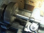
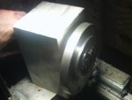
My lathe is a 12x24 unit, meaning that I can chuck something up to 12" diameter and up to 24" long. The bed is much longer but part of the bed on the left is taken up by the headstock and some of the bed on the right is taken up by the tailstock.
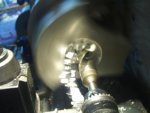
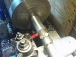
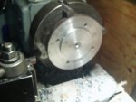
I also have a second tailstock for it which is a "turret tailstock", and that's for mass production of parts. Instead of one MT2 (morse taper 2) socket that's extendable via a crank, the turrent is octagon shaped and has eight such sockets. I can insert different tools into each of the eight sockets, then rotate the tailstock to whichever tool I need to present to the material. So with my machining of the rear spindles, I could have put the live center in position one, a center drill in a chuck in position two, a 37/64" drill bit in a chuck in position three, and so on and significantly reduce the time it takes to set up the tooling each time. I had it on the lathe for the longest time and used it quite a bit until recently where I needed to machine a 24" long axle shaft and the turret tailstock is much longer than the "ordinary" one so I swapped them out. Swapping them is a pain in the butt because the turrent tailstock has to be realigned every time, where as the ordinary tailstock just bolts onto the bed and self-aligns.
$3500 is only about 50 hours on the machine. Just enough for me to justify buying my own machine and spending 5 times the amount of time to do half the job they would do in a pro shop.
")
yes, that's one way of looking at it and that's how I ended up with a lathe and a vertical mill. There are some steps in things I make that requires a machine I do not have, and that I'll send out. Like surface grinding, I don't own the machine so the once in a blue moon where I need something surface ground to a thou or better I'll farm that out. I probably farm a job like that out once every few years, so buying a big-arse machine and having it take up valuable space is not worth it to me.
It's all in the experience right? Granted I might still need to pay a shop for things where a few thousandths count, as You said.
Experience does count, absolutely, but one thing many amatuer machinists forget is how important the math is. For example, you know that the radius of a circle is half the diameter. Almost everyone knows that. However if you're not paying attention, and you need to enlarge a bore exactly 1/100th of an inch, you'd be very tempted to move the dial exactly one line, which is 1/100th of an inch.
Except, since you're machining a bore, you're actually cutting off 2/100th of an inch.
While this seems like an incredibly stupid mistake, I cannot count the number of times I've borked that completely. It's very, very easy to do.
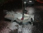
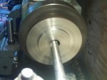
One thing you may notice in the video (I did mention it) is that I always cut away from the chuck if possible. Why? Because exactly once, just before the cutter that was skimming down a long shaft, the phone rang and in telling that person I'd get back to them in about 10 minutes, the lathe cutter went all the way to the chuck, hit the jaws, and broke off in a way that it ended up embedded in the tool holder. I didn't care about the cutter as it was about $6 worth of tool steel, but losing a $60 Aloris tool holder sucked and the $180 piece of aluminum that was chucked was also toast. And, things like this are easy to do. That's one of the reasons why I cut as slow as I do. It gives me the opportunity to correct mistakes before the mistake ruins a lot of stuff.
I am going to making mine out of a old beer keg with a kind of fire cement plastered inside. Fueled by waste oil such as motor oil, frying oil etc.... Probably won't get as hot as the acetelyne/oxy furnace though. Mine won't rotate, although it's worth thinking about.
The rotation thing makes it easier to pour as it's on a stand therefore no tongs are necessary. The ace/oxy fuel system I thought was gross overkill, but then again my buddy was comfortable machining all the jets and whatnot and the end result is that it melts large quantities of aluminum fairly fast, which lowers the overall cost in fueling. Obviously if it can melt a crucible of aluminum in 20 - 45 minutes that's more economical than if it has to run for hours.
Fantastic work on the second video! Explains my questions precisely.
Thanks!
akes sense now. Makes me want to be able to use a boring bar more often. I'll have to make do with a drill bit. I can make reasonably accurate holes with the drill bushings I have.
Just remember that twist drill bits do not make round holes, but round-like triangles. We're talking small tolerances here, in the "few thou" range. But sometimes, this makes a huge difference between junk and quality. It all depends what you are making.
A boring bar gives a very precise finish, especially when the work moves quickly and the cutter moves slowly. The finish is even better when cut wet, which I rarely do unless I'm machining tool steel or something harder.
You can only use a drill bit on a mill correct?
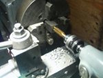
Um, no, you can use them on a lathe, I do it all the time. There's two ways of doing it that I know of. One is to buy a chuck for your tailstock, which replaces your live center. Chuck the work into the lathe's chuck, then drill the hole. It's backwards in a sense because the bit is stationary and the work rotates.
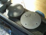
Another method is to buy a drill chuck on a tool holder, and use it with your tool post. Then you'll have to align it to center every time but when you need to drill off-center holes in precise locations, you can do that. An example of this would be drilling stud holes in a wheel plate for a hub. The four or five bolts that the rim bolts to are off center. So you'd move your lathe's crossslide then drill, using the accuracy of the lathe dials to precisely place that hole. The lathe's chuck of course isn't rotating and should be locked, as you're using it more like a rotary table.
Does that make sense?
You can't spin the piece and have a stationary cutter like a boring bar. Is this why you used the lathe for the accuracy?
This is how a milling machine operates - the work is stationary and the boring bar rotates in the work to make the hole. The difference is the boring bar is called a boring head, and is shaped a little differently and maybe has some additional features other than 'stiff' and 'cutter goes here'.
Are you going to be using a locking collar to hold the axle in the bearing?
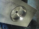
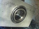
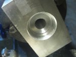
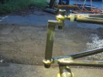
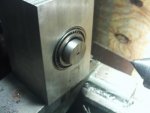
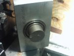
The axle will fit snugly in the bearing, and the axle will be located left to right by the things attached to it. The wheel plate which will have the wheel studs inserted will be welded to the axle, so the outer bearing will be held in place. On the inside, there will be a larger diameter collar attached which will hold the inner bearing in place (adjustable tension of course) as well as provide a mount for a CV or a U-joint depending how that all works out. I'm still mulling that detail in my head, but yes, the tapered bearings will be locked in place with adjustable tension the old fashioned way - castle nut and cotter pin, more than likely.
Any progress on the rest of the suspension?
I added two posts this evening with pictures so that's the progress that's been made.
Thanks again for documening all this, hope it isn't making the work too slow.
Sure, happy to help and share knowledge. It did slow me down a bit though not so much while machining, but mostly I lost machine time after my son goes to bed as I was monkeying with the video. Seemed my software didn't like my camera's .mov format at first, and I had to tweak something to make it work.
It's cool though, I was happy to do so.