Budget stock 212 Hemi TORQUE MONSTER build!

Messages
143
Reaction score
10
Hey everyone! Welcome to my engine build thread. As the title implies my goals are to take a Predator 212 Hemi and try to improve the low and mid range power while not giving up very much (hopefully none) power in the higher rpms. The plan is to keep the stock cam, rod, piston, flywheel, valve springs... Basically all of the internals will be stock. Governor will be completely removed. Stock intake and exhaust will be removed and replaced with custom made scrap and carberator will be replaced with a el'cheapo 21mm Continuous Velocity unit. Various aspects of the engine will be reworked in order to try to achieve more low and mid range power and improve throttle responsiveness. This is an experiment to gain efficiency so I would not recommend doing so until it is proven to actually work. I have not seen anyone else try much of the things I am planning and there is probably a good reason for it. So just you understand, that was your warning! So don't blame me if you screw your stuff up.

The kart that we are going to use this on is a heavy old homebuilt unit. Since we have a small yard and the kart has to not only repeatedly take off from very slow speeds very often, but will have to do so with heavy adult riders as well children and teens. The maxium speed that our yard can hold is about 20mph taking into consideration some distance to slow down to turn. So even if we give up a tiny bit of power up top it won't really be noticeable 95% of the time since we probably won't see rpms above 4,500 too often. We could gear the kart to max out the rpms until the valves float just near the end of our longest stretch but it would be a very jerky kart that would likely not be able to get traction, would be very hard on the torque conver and be very difficult and pretty unsafe for younger riders. We will build it so that the clutch can engage properly with minimal wear, have smooth acceleration and wherever the top speed falls is where it falls. Probably about 28-32mph or a little more. As long as it pulls hard but smooth in our yard we don't really care about top speed.

A bit more about the engine. I am going to try to incorporate a few "speed secrets" to gain more power in the low and mid rpm range where this engine will be used the most. Some of these things might be beneficial and some or all may be detrimental to the overall efficiency and reliability of the engine. I am just experimenting with what I think will work... It may not. Time will tell. There are as many opinions of what is right or wrong as much as there are theories about what works and what doesn't. I am just going to test my own theories and see if I am right or wrong.

Some of the things I will be trying to successfully incorporating include:

-Proper velocity intake and exhaust ports for the stock engine combination
-Tuned intake runner to make better use of the higher velocity ports
-Tuned exhaust
-Possibly a plenum design
-Polished piston, combustion chamber, valve faces and exhaust port
-Anti-reversion ports
-Lapped valves to ensure proper valve sealing
-Some light mods for better cooling/oil penetration and oil return
-Might do some other polishing just because it's so satisfying to see shiny stuff! Lol

There are other things that I will probably do that I forgot to mention but that gives you an idea. Now the proper way of trying new things out and seeing if each one actually has a positive effect is to test the base model, record tge results and then change one thing, test, record and repeat the procedure. A dyno and flow bench with repeatable results would be a great way to fully examine each step of the process and help fine tune things as I go along but I don't have them so I'm just going to jump in, try my best and see what happens. Afterwards I will purchase another brand new 212 hemi, replace the intake and exhaust with the very popular off-the-shelf kit, remove the governor, and switch out both engines on the same kart with the same clutch and keep everything the same and see if there was any gains or losses in doing all that I did.

Stay tuned!
[/SIZE]

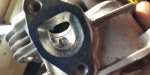
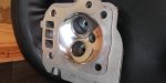
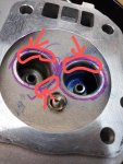
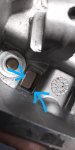
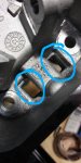
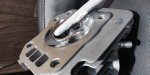
Here is some of the port work so far. It's not done but it gives you an idea of what I am doing at this stage. I have removed material from the short side radius bend and around the valve stem to increase laminar flow to the valve seat. The removal of the material increases the cross-sectional port area adding more total volume for air to flow through it. However, the larger volume of space for the air/fuel mixture to move through can be beneficial at allowing more total cubic feet of air per minute (CFM), it also lowers how fast the air/fuel mixture will sweep through (Velocity) given the same amount of low pressure/high pressure differential during all phases of the valve and piston events (movements).

The exact spot where I removed material from the short side radius and valve stem shouding was the smallest cross-sectional area in the port, effectively making it the "choke point". At that point when the air/fuel mixture went through it would speed up and increase velocity. The reduction of cross-sectional area causing the air to speed up is refered as the Bernoulli Effect if you want to look it up. Be cautious not to remove too much material if you try to do port work because it can lower the port velocity, which in turn can cause seperation of the fuel dropplets from the air (because fuel is heavier and harder to effectively move from one place to another suspended in an air current) and you will loose efficiency. The fuel must remain seperated in small dropplets with the correct amount of air in between the fuel dropplets so that when they reach the combustion chamber, become compressed and a spark is introduced, the dropplets of fuel can ignite very quickly. Since fuel is a liquid it has surface tension and the bigger the dropplet is the more surface tension it has and is slower to ignite and burn (That's just one reason, there are more but this is already too much too read for most people). If many little dropplets are allowed to bump into one another in the journey to the combustion chamber they will collect together into larger, harder to ignite dropplets and slower burning dropplets. So faster air currents are more effective at keeping fuel dropplets suspended in the air and seperated than slower currents are. Hence, keeping proper port velocity is important. There is more to it than that but it should be enough to get the point across as to one reason why lower velocity air flow usually leads to a less efficient fuel/air mixture. Also, a higher velocity current is much more efficient (faster and packs more air in per timescale) filling a space than a slower air current. More air, more fuel, more POWER! It is more pronounced at lower rpms but can affect efficiency at all rpms.

Ok, it was at this point in my imagination when I was contemplating doing some port work that I thought "Well if I do that then I am removing the "choke point" and I may end up severly reducing velocity. These ports look to big as they are, especially the valve bowl.. so if I do this I may want to add material to improve velocity." That's when I started searching around for what others have done to prevent too low of velocity. I couldn't find anyone who had tried to tighten the ports up to improve velocity. So I thought "Well, maybe I will try it and see if I can gain some performance in the low and middle rpm range where it seems like this engine is lacking power. Maybe thats the reason? Or I'm wrong and I screw it up."

So, second guessing myself, I got the engine event specs and sizing of the various parts to determine valve events, piston speed, port cross-sectional areas at various spots, CFM needed, etc, etc, etc math-formulas-theories, blah blah blah and it seemed like the numbers agreed with me. That's when I made my other post on here asking others for advice and answers. I think the consensus is that these little engines don't quite play with the same rules that other engines do... But then, maaaaaybe they do.

So here we are. I guess I'm going for it!

Port work progress
 

Attachments

  • 20200626_021052_HDR.jpg
    20200626_021052_HDR.jpg
    163.9 KB · Views: 31
  • 20200626_002213.jpg
    20200626_002213.jpg
    158.3 KB · Views: 30
  • 20200626_002201.jpg
    20200626_002201.jpg
    120.5 KB · Views: 25
Last edited by a moderator:
Messages
143
Reaction score
10
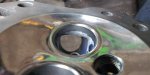
Oh yeah, you might have noticed the shinier combustion chamber in the pics above. I took some time to do some very light de-shrouding work around the valve seats, some sanding and some polishing to the combustion chamber. Since these are Hemispherical heads there really is not much reason to do any "de-shrouding" around the valves/valve seats because one of the main advantages inherit to the hemi head is that as the valves open they move further away from the surface of the head in all directions. At this level of "performance" any gains of flow due to de-shrouding would be drastically off-set by loss of compression due to a larger combustion chamber.

So basically I just wanted to blend the tiny little ridges down where the surface was slightly above the surface of the valve seat. At low lift (when the valve just begins to move away from the valve seat) the air rushing in will flow tightly across the surface of the head. If you can help the air move more efficiently then it will aid in filling the chamber faster. The flow of air will flow across the surface and then down before sweeping to the center. This motion is like a swirling in all directions and helps not only fill the chamber faster but also keeps the air and fuel seperated so that the fuel dropplets don't adhere to each other as much making a slower burning charge and flame front. This is another inherent positive function of the hemispherical head design.

So to try to help facilitate laminar flow from the valve seat and reduce any turbulence that might affect efficient swirl I smoothed out the tiny ridges. Also because I am just a tinkerer and want to tinker the tink out of everything. Then I sanded and polished for the same reason... Plus it ljust looks awesome.

More on the polishing point, there are many different opinions and theories, and opinions about the theories about polished combustion chambers and other polished parts and pieces. Do some research and be ready for all the differing theories, opinions and comments if you decide to polish anything.

My thoughts on it are that it helps to retain heat in the combustion chamber, reduces hotspots, reduces surface area for carbon to cling to and when carbon does build on it the hotspot it could creat is dissipated more efficiently across the surface. Also since the surface is smoother the carbon build up will be smoother and should, in theory, decrease the escalation of build up compared to the escalation of build up that would occur on a non polished surface. In addition to the above mentioned, the air swirling across would have a more smooth surface allowing more laminar and faster flow... In theory... In my head.. so I figure there is more possible benifits than possible down sides to it and since I will be trying to optimize the velocity and efficiency of the exhaust flow that any retention of heat that might cause over-heating from the polised surfaces not dissipating the heat as efficiently through the components will be countered by the more efficient exhaust. And one last thing, since the fuel (regular low grade gasoline) that I will be using is pretty slow and difficult to burn very quickly when you take a close look at in the big picture scale of things you have to keep a certain degree of heat within the head in order to make the combustion process more efficient. Plus is is less susceptible to being scratched or dinged up while doing port work and the like(or just setting around on the bench) Ok, that's enough. Take it all with a pinch of salt. I did it. It looks cool. I was bored. It might help, might not. But it's done and we can move on. (Can you tell that this has brought issues up with me before with folks? Lol)

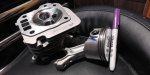
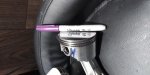
Oh yeah, polished the top of the piston too.

For reference here is a before picture highlighting a few of the ridges around the valve seats and a comparison of the surface before sanding and polishing. It's not perfect but definitely an important.

Another thing that I have done is worked the pushrod/oil channel splash tunnel area. I noticed some flashing on the edges of the channel. I ground them off flush and then added a little bit of a taper to the top of the edges on the rocker arm side to improve the slippage of oil back down to the block. It should allow the oil to be splashed up easier and slide back down the surfaces a tiny bit more efficiently. I only removed a very little amount so as to not cause a weakening to any of the spots that I removed material from. Just enough to make a little bit of difference. I might sand down and polish the bottom side that the oil will most likely be sliding back down to improve flow on the surface. I haven't seen this done before either so there might be a good reason not to do this. But again, in theory, in my own mind, it made since to do it.. So I did. I could be wrong.

I will start work on the exhaust port, finish up the intake port and then do some measuring. Do some math, plug in some numbers and try to formulate where I want to go from there on the shape, size, contour, angles and so on for the ports. Given the angle of the head position, position of the ports and being a hemi head there are a number of things to consider with exact angle, sweep, position of radii's, etc that are specific to this application which makes it unique and challenging.

Let me know your thoughts so far and any ideas you might have.

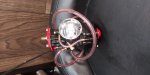
Here's the carb that I will be using. I actually meant to order a different 21mm carb that is more like the type of carbs they use on GY6's and Harley Davidson's where it has throttle controlled butterfly and a velocity controlled slide because I think it would be better suited for the throttle response, low to mid range rpm control and smoothness that I am looking for on this build but I had this one and the other one in my online cart and ended up ordering this one accidentally in a rush. Oh well. It should be fine. I went for a 21mm because I am looking to keep the velocity up through the entire intake from carb to valve seat plus 21mm is more than enough for volume at the maximum flow needed for this build. Plus I like being different... And it was cheaper than a 22mm Mikuni. This is a Maikuni. Lol Oh yeah, I polished the intake side of the carb too. Yes, I may have a problem. Once you polish something and see the results you will find an excuse to polish the dumbest chit you can find. Lol
 

Attachments

  • 20200627_012008_HDR.jpg
    20200627_012008_HDR.jpg
    163.9 KB · Views: 20
  • 20200627_012237_HDR.jpg
    20200627_012237_HDR.jpg
    175.4 KB · Views: 19
  • 20200627_012227.jpg
    20200627_012227.jpg
    188.9 KB · Views: 19
  • 2020-06-27 05.07.54.jpg
    2020-06-27 05.07.54.jpg
    190.8 KB · Views: 22
  • 20200623_230029~2.jpg
    20200623_230029~2.jpg
    294.2 KB · Views: 23
  • 20200626_011901~2.jpg
    20200626_011901~2.jpg
    191.7 KB · Views: 17
  • 20200626_011749~2.jpg
    20200626_011749~2.jpg
    132.3 KB · Views: 15
  • 20200626_013334_HDR~2.jpg
    20200626_013334_HDR~2.jpg
    233.6 KB · Views: 15
  • 20200627_054918.jpg
    20200627_054918.jpg
    224.2 KB · Views: 19

itsid

Moderator
Staff member
Messages
11,563
Reaction score
246
Location
Ruhrpott [Germany]
Let me know your thoughts so far and any ideas you might have.

thoughts?
"God that textsize is annoying!" :smiley_omg:
Also:
no double posting please when you can avoid it by clicking the edit button!

So unless you reached ten pics or 10k characters, click the edit button and do not start a new post ;)


'sid

PS haven't read the content, because of that terrible font size you picked
 
Messages
143
Reaction score
10
thoughts?
"God that textsize is annoying!" :smiley_omg:
Also:
no double posting please when you can avoid it by clicking the edit button!

So unless you reached ten pics or 10k characters, click the edit button and do not start a new post ;)


'sid

PS haven't read the content, because of that terrible font size you picked

It looks only slightly larger and a tab bit easier to read to me. What about the text size is annoying? What size should I pic? I didn't see that I double posted. I tried to edit a pic to rotate it and when I couldn't rotate it I rotated it and then re-upload it and delete the other post but it said that it would be a double post and to me the second post never showed up.

---------- Post added at 12:10 PM ---------- Previous post was at 11:56 AM ----------

Oh, I see what you did. You combined all of my seperate posts into just 2 big posts. I don't know why it is a bad thing to seperate different components into it's own post with it's own pics. Now it's difficult to relate each thing separately and there is much more to read at once. I don't think there was anything wrong with the way I did it.
 

karl

Well-known member
Messages
2,448
Reaction score
717
Location
North east Ohio
It looks only slightly larger and a tab bit easier to read to me.

Are you using a 4k resolution monitor/ desktop? Or a huge screen?

At 1080p, its painful to read , I got about 2 lines down and had enough.

Poor sid is still rocking windows XP, probally on an old CRT, so yeah, each line of text is a couple words.

Just stick with what the forum preset is , everybody can read it fine here. And dont forget the return key!
 
Messages
143
Reaction score
10
Are you using a 4k resolution monitor/ desktop? Or a huge screen?

At 1080p, its painful to read , I got about 2 lines down and had enough.

Poor sid is still rocking windows XP, probally on an old CRT, so yeah, each line of text is a couple words.

Just stick with what the forum preset is , everybody can read it fine here. And dont forget the return key!

Thanks karl! That gives me an idea of which way (too big or too small) that I went. It used to be that you got yelled at for not bumping up the font size here because the normal size was too small with larger paragraph. I guess the forum has undergone format changes since years ago. I just went with what I thought was better. It looks great on mobile browsers... Just slightly bigger than normal. I will adjust promptly and not mess with it from normal.

P.s. Way to go sid, windows xp rocks. CRT monitors blow so that sucks.
 

itsid

Moderator
Staff member
Messages
11,563
Reaction score
246
Location
Ruhrpott [Germany]
It used to be that you got yelled at for not bumping up the font size here because the normal size was too small with larger paragraph. I guess the forum has undergone format changes since years ago. I just went with what I thought was better. It looks great on mobile browsers... Just slightly bigger than normal. I will adjust promptly and not mess with it from normal.

P.s. Way to go sid, windows xp rocks. CRT monitors blow so that sucks.

I can't remeber anyone being yelled at for using the std size;
and yes this forum is not optimized for phones..
so more stupid phone-browsers don't know what to do with the font size.
(better ones have a small slider tucked away somewhere where you can just nicely dial in the browsers font size to legible formats for you and you only)

What I do know however that the forumsoft is in it's stock size configuration exactly as it was when freshly installed.
(I do not know if it ever was messed with.. I doubt it was tbh)

And yeah.. xp is indeed my go-to typewriter and I kinda like my 19" Belinea CRT as well (although it indeed shows signs of age now... had to bump up the gamma quite a bit to get the luminosity I am used to)
very different topic though ;)

'sid

PS Thanks for scaling that down to legible sizes again.
it was terrible on all devices inkl my phone btw..
 
Messages
143
Reaction score
10
Ok, so at this point in the build its time to try to figure out the optimal port size (internal cross-sectional area at various point along the length and total port volume) for the engine combination (cam specs, bore, stroke, rocker ratio, piston speed, valve events, and how all the events work together) and desired goals of rpm range you want to tune for. Along with the port area you also need to factor in or determine intake runner as well as exhaust manifold/header size and lengths. Many applications you are dealing with a static runner size and length as well as exhaust size and length. Both can be adjusted to move the torque curve above or below the port tunning but it's best to try to tune the entire system together if possible... Which is what I will try to accomplish. There are some limitations with lengths but I can adjust the entire system to try to reduce the tunning compromises those limitations will effect in the desired goals.

The cam is very important to how you tune your ports. You must either tune your ports to your cam or get a cam that is better for your goals and then tune for that cam. You can't just tune ports, intake and exhaust to optimize for goals that your cam disagrees with or it's very likely that you will end up with muddy performance all around. So with that said, I am tuning for the stock cam to optimize what the cam is already good at.

Once you get the necessary engine specs you can use them to basically calculate how your engine pumps air. The characteristics of your engine and how it pumps air determines how much and how fast your engine can pump air to fill your specific combustion chamber size. The port length, volume and position of various cross-sectional areas within the port will have a great affect on how the air traveles to reach and fill the combustion chamber. It's critical to match the dimensions of the ports to the cam, piston size, stroke, piston events (piston speeds and point of position relative to event cycle), etc so that you can enhance the air/fuel mixture flow and velocity to the specific desires of the power range. You want to keep the total volume of air that can be moved through the port enough to flow the maximum amount of air that the engine will need but keep the velocity of the air up enough to prevent fuel seperation without becoming so fast that you begin to introduce a sonic choke (which is basically where the air moves so fast that it fills tge combustion chamber too fast and the pressure in the combustion chamber matches or exceeds port pressure as tge piston is still moving away from the head. It creates a choking that becomes detrimental to efficient filling of the combustion chamber. There are other "sonic choke" events but that's one scenario) condition that adversely affects cylinder fill.

So that's a basic rundown of the why to what I am going to be trying to balance and "tune" for right now. Some other things that you have to keep in mind and try to achieve concerning porting include:

-Anti-Reversion. This is where you try to produce a port that flows optimally in the correct direction but not as well in the reverse direction. For instance an efficient intake port would allow the right amount of fuel/air mixture to fill the cylinder at a proper rate of speed and volume and would be resistant to the charge reversing as the piston comes up to compress the charge before tge valve finishes closing. Also it becomes important buring "overlap" where the exhaust and intake valves are open at the same time. This will help prevent exhaust gases or air trying to charge up the intake and disrupting the flow coming down, prevent it from the engine wasting energy to pump already hot and used air and prevent heating the incoming air/fuel mixture and intake track since cooler air is more dense it can pack more oxygen per cubic space compared to warmer temps. Oxygen is needed to burn fuel. The more oxygen that is present the faster and more efficient the fuel burns. The faster and more efficient the fuel burn is the more efficent each combustion is. More efficiency, more POWER! Efficiency is king. Also, if port velocity is too slow it can enhance the possibility or make reversion worse.

(Research the upcoming terms to get a better and more accurate description. I will try to explain them accurately to the best of my knowledge and ability to put the theory into words)

-Swirl. It's important to have laminar flow but if you can get tge air to "Swirl" it can be beneficial in aiding the air/fuel ratio to stay seperated and atomized (where the tiny fuel droplets and air molecules retain seperated in smaller parts and there is a proper amount of air around each fuel dropplet, effectively keeping the fuel combining into too large of dropplets. This is the goal for the most part. Too small of dropplets and the whole mixture become too expanded and takes yp too much space to properly fill the cylinder. This is usually much less likely a concern but is something to try to avoid as well). Proper swirl will also aid in proper flow past the valve and valve guide efficiently and help in efficient cylinder fill. There is also swirl that pertains to the valve/valve seat and cylinder fill.

-Tumble. Tumble is similar to swirl in a way. This is a way to have the A/F mixture "tumble" in a way to prevent fuel seperation without affecting flow or introducing too much unwanted (uncontrolled) turbulence. It's kinda like an engineered, specific and controlled slight turbulence that you introduce in a way that helps usually in keeping the fuel dropplets suspended in the air stream and preventing it from collecting on the floor or walls while aiding in proper A/F ratio mixture.

-Boundry layer. The boundry is a layer of air along the port floor and walls that can help keep fuel from coming in contact with the floor or wall. You can try to manipulate or build a boundry layer by purposely roughing up or building a deliberate non smooth surface to entice an effective boundry layer.

There are more but these are some of things that I will try to keep in mind and/or incorporate into the ports.

---------- Post added at 04:57 PM ---------- Previous post was at 04:49 PM ----------

I can't remeber anyone being yelled at for using the std size;
and yes this forum is not optimized for phones..
so more stupid phone-browsers don't know what to do with the font size.
(better ones have a small slider tucked away somewhere where you can just nicely dial in the browsers font size to legible formats for you and you only)

What I do know however that the forumsoft is in it's stock size configuration exactly as it was when freshly installed.
(I do not know if it ever was messed with.. I doubt it was tbh)

And yeah.. xp is indeed my go-to typewriter and I kinda like my 19" Belinea CRT as well (although it indeed shows signs of age now... had to bump up the gamma quite a bit to get the luminosity I am used to)
very different topic though ;)


'sid

PS Thanks for scaling that down to legible sizes again.
it was terrible on all devices inkl my phone btw..

Although there were others that mentioned scaling the size up some, especially on long paragraphs they also would mention double spacing it was usually poboy kartman and company complaining about it.

Nice CRT. I see your point using the CRT now. Very nice.
 

itsid

Moderator
Staff member
Messages
11,563
Reaction score
246
Location
Ruhrpott [Germany]
Again, I think I read nearly all of Doug's posts
and while he liked to complain about walls of text, missing punctuation etc. quite alot;
I cannot recall him asking for a bigger font size
(not saying he hasn't.. just saying I don't remember it being "a thing" he complained about -at least semi-regularly)
He asked alot for smaller or bigger pictures though (depending on people just sharing thumbnails instead of pic, or embedding 32MB jpgs to show a bolthead)
So maybe a misread complaint?

Nevermind! doesn't matter nearly enough to spoil this thread :D


You certainly read about the polishing dilemma..
and came to a conclusion for yourself.

I did too and came to the opposite conclusion though ;)
I once saw a video about port polishing once that was amazing,
the guy not only explained it very well,
but also put it to the test.. and in fact "rough" surface (in his setup) is better,
especially since laminar flow is easier to achieve with miniscule guiding fins on the sidewalls (made by directional sanding)
testobject back then was a VW bug engine's head.
The idea behind it is to look at what nature does to reduce turbulence and drag
shark skin is textured, or butterfly wings etc...

Anyhow, there are still some that do the opposite and achieve positive results.
some grind just against the direction of flow
in order to add turbulence for a better fuel air mix if air-speed isn't an issue
(especially popular on looong intake manifolds)
some polish to near mirror finish to get the balance between good speed and a good mix.
(both can be seen on F1 engine's intakes over the past years)

but on short intakes.. port polishing nearly vanished since the seventies
and directional grinding and sanding took it's place almost everywhere.

I think the same holds true for the combustion chamber tbh..
a perfectly smooth surface is terribly sticky (like saran wrap is perfectly smooth)
very fine textured surfaces are the opposite (like a lotus leaf is covered in miniscule spikes)

And while one cannot just recreate a Lotus leaf texture in the home shop of course,
it's a matter of finding what get's closest with a reasonable amount of effort.
IMHO a dull finish (say fine grit steel wool making tiny circle patterns or so)
is preferable,
but one would have to actually test different finishes in a controlled way to actually make a call for that particular tested setup in the end.
Something that's way too much effort for a home shop IYAM.

So in my head I have to disagree
(I find the "do as nature does" theory very plausible.. hence dull and rough instead of smooth and shiny)
in practice I bet you'll be fine and won't notice too much of a difference anyways.

'sid
 
Messages
143
Reaction score
10
:auto:
Again, I think I read nearly all of Doug's posts
and while he liked to complain about walls of text, missing punctuation etc. quite alot;
I cannot recall him asking for a bigger font size
(not saying he hasn't.. just saying I don't remember it being "a thing" he complained about -at least semi-regularly)
He asked alot for smaller or bigger pictures though (depending on people just sharing thumbnails instead of pic, or embedding 32MB jpgs to show a bolthead)
So maybe a misread complaint?

Nevermind! doesn't matter nearly enough to spoil this thread :D


You certainly read about the polishing dilemma..
and came to a conclusion for yourself.

I did too and came to the opposite conclusion though ;)
I once saw a video about port polishing once that was amazing,
the guy not only explained it very well,
but also put it to the test.. and in fact "rough" surface (in his setup) is better,
especially since laminar flow is easier to achieve with miniscule guiding fins on the sidewalls (made by directional sanding)
testobject back then was a VW bug engine's head.
The idea behind it is to look at what nature does to reduce turbulence and drag
shark skin is textured, or butterfly wings etc...

Anyhow, there are still some that do the opposite and achieve positive results.
some grind just against the direction of flow
in order to add turbulence for a better fuel air mix if air-speed isn't an issue
(especially popular on looong intake manifolds)
some polish to near mirror finish to get the balance between good speed and a good mix.
(both can be seen on F1 engine's intakes over the past years)

but on short intakes.. port polishing nearly vanished since the seventies
and directional grinding and sanding took it's place almost everywhere.

I think the same holds true for the combustion chamber tbh..
a perfectly smooth surface is terribly sticky (like saran wrap is perfectly smooth)
very fine textured surfaces are the opposite (like a lotus leaf is covered in miniscule spikes)

And while one cannot just recreate a Lotus leaf texture in the home shop of course,
it's a matter of finding what get's closest with a reasonable amount of effort.
IMHO a dull finish (say fine grit steel wool making tiny circle patterns or so)
is preferable,
but one would have to actually test different finishes in a controlled way to actually make a call for that particular tested setup in the end.
Something that's way too much effort for a home shop IYAM.

So in my head I have to disagree
(I find the "do as nature does" theory very plausible.. hence dull and rough instead of smooth and shiny)
in practice I bet you'll be fine and won't notice too much of a difference anyways.

'sid

Thanks 'sid.

Yeah, In the end my intention was to make the thread easier to read for people but it backfired. It's fixed now and I have learned my lesson.

As for the polishing I won't be polishing the intake. I will polish the exhaust. I strongly agree with, and have always tried to gain insight by looking to nature for the best way of achieving efficiency. As for the combustion chamber it is not completely smooth. There are still traces of the origional texture and the constant curvature of the hemispherical head helps to resist carbon build up because of the constent curvature. The superficial peaks of the surface was sanded to reduce the total area for carbon to stick to. It still might not help or I may have made it worse but it is an experiment in itself to see how much carbon builds up. I will pull the head off periodically to check. Plus, it just looks cool and I have a problem with wanting to polish everything lol I do hope that it reduces specific hopspots by more efficient heat transfer across the surface of the piston and head portion of the combustion chamber though as well as retain proper heat within the combustion chamber leading to more efficient and quicker burn cycles, hopefully without causing overheating issues or pre-combustion events. I don't think there is a strong enough effect for it to lead to either of those but it's still a concern.

I think I will try some engineered "rough" small channel walls to induce a strong boundy layer and try a sleek fuel sheer that won't cause unwanted turbulence or affect total flow efficiency. I'm going to try to do just enough to make a difference without doing anything too drastic that will totally screw everything up. Time will tell.

Thanks for the input though! I might pull back on over smoothing/polishing the exhaust port. What is your opinion on polished valve faces, polished exhaust back side and valve stem?

Any other opinions?

---------- Post added at 01:17 PM ---------- Previous post was at 12:19 PM ----------

I have been crunching numbers and then crunching the crunched numbers, reevaluating the variables and crunching some more. I am trying to come up with the biggest cross-sectional average area port to support the most horsepower this engine will be capable of to be sure that I don't tighten up the ports too much.

Running the numbers as accurately as I can and being generous with the variables in the favor of larger porting needs I still come up with a port cross-sectional area smaller than stock. I feel that I may be underestimating what this engine will produce with a new carb and exhaust. I am trying to find dyno results with 212 hemi with cv carb, high flow header and smaller head gasket. It seems like it goes from box stock pulls to aftermarket cam pulls.

Well until I find some good source of info on the power it makes the the configuration I will be running I am hesitant on moving forward. Until then I guess I will Gab more! Lol

As of now the numbers say that a maximum diameter cross-sectional area (inces squared) is about .478" and my crude calculation of the intake port entry is about .671". Now my method might cause a minute discrepancy of the actual EXACT port area it is obvious that it is larger than .478" and while the port does taper some it is still too big of an average port area that the numbers are saying at .426" for the average. I am aiming for about 260 fps average with a peak of about 285 fps at the choke point at the fuel shear. The difference may not seem that big of a deal but when dealing with flow, velocity and keeping fuel aloft and suspended properly within an air current it could make a good amount of difference.

I used a better efficiency because if you look down the port and imagine a smaller port you can see that if you knocked down the short turn radius cliff you could have a straight shot to the valve seat. This would greatly improve laminar flow over stock to the point where total calculated CFM would be greatly improved with basically zero obstacles or turns/bends. Even the valve shroud could be trimmed flush only leaving the valve stem as the only obstacle. Of course the valve bowl would have to be adressed.

But here is the question that I want everyone's advice on:

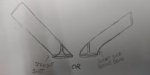
Is it a better to have a completely straight port at an angle to the valve seat or better to have a gradual bend on the short turn radius approaching the valve seat when you factor in swirl, tumble, etc?
 

Attachments

  • 20200628_133817.jpg
    20200628_133817.jpg
    118.3 KB · Views: 10
  • 20200628_140124.jpg
    20200628_140124.jpg
    75 KB · Views: 10
Messages
143
Reaction score
10
With a straight shot to the valve seat I could angle the port to miss the valve stem but if I add a gradual short radius I would reduce the angle so that I could add a gradual bend to the short side entry as well as a gradual turn to the long side entry to the valve seat. I am thinking it will produce more flow around the total circumference of the valve with a short and long side gradual bend and would provide better swirl and cylinder fill. But then again, the straight shot with plenty of velocity might prove to be better. Hmm... Your thoughts???
 

itsid

Moderator
Staff member
Messages
11,563
Reaction score
246
Location
Ruhrpott [Germany]
well valve stems polished of course.. for the valve guides alone ;)

back and face I honestly do not have an opinion on that..
they're interfering with the airstream anyways just because of their shape,
I'm not sure you can do much about that either way.
Since the valves are opening and closing gradually and do not just snap open/closed
you will upset the airspeed and direction no matter what you do.

for a rotary valves I think I'd go for a straight shot approach,
for poppet valves a bend is likely working in your favour.
Reason being the general direction of flow should be as straight against the valve as possible,
so that passing air is spread evenly in all directions.
a gentle curve in the intake port of such poppet valves is a good thing really;
and that holds true even for the exhaust port
In you picture the air would favour the right hand side when the valve is open,
since itself is acting kinda like an air foil.
in case of the intake port it'd lead to an uneven fill and thus likely an uneven combustion;
and in case of the exhaust port the gases entering the port from below,
would hit a wall while slowing down the gases entering from the right.

'sid
 

Brianator

Gettin' er done!
Messages
860
Reaction score
18
Location
Barrie, Ontario, Canada
I like your idea of polishing the combustion chamber, piston and valve faces to ward off carbon deposits!

I "gasket match" the complete intake tract on any motor I tear down (because I can and want to) and every one big and small just seems smoother and happier to me. I leave a (perpendicular) 400 grit finish on small engines and usually a little coarser for automotive, moreso when they're carbureted.

For the exhaust side I still leave a sanded finish but pretty smooth (1500/2000 grit) because the "boundary layer" adds "lubrication" of sorts, 'sids comparison to saran wrap (sticky) is brilliant!

On the intake we know we want smooth, laminar flow across the ports which makes anti reversion difficult but not impossible... a proper "tuned" length of intake tract already has it build in by design. Reversion is in essence the sound wave travelling back and forth from one end to the other, "tuned" intakes (and exhausts for that matter - more on that coming up) have long, complicated equations that come into play so that sound wave will bounce off the valve right when it fully closes as to speed up the air down the tract while not disrupting the airflow into the chamber and is calculated in "waves" (1st wave 2nd wave ect.) based on the length but that's far too complicated for anything less that a full out purpose built racing engine!

The exhaust on the other hand works on the same principles but the goal is to have the wave revert off the head JUST before it opens as it will help draw the gasses out quicker (exhaust "scavenging") which helps draw in a little extra fuel charge during valve overlap. Anti-reversion (into the cylinder) on the exhaust is easy, make sure the exhaust port exit mouth on the head is a little smaller than your flange and pipe and that's it! The sound wave will bounce off of it instead of getting to the valve :2guns:

I for one will be following along because I think you're on to a cool experiment that you've put alot of time and thought into, bravo! :wai:
 
Messages
143
Reaction score
10
well valve stems polished of course.. for the valve guides alone ;)

back and face I honestly do not have an opinion on that..
they're interfering with the airstream anyways just because of their shape,
I'm not sure you can do much about that either way.
Since the valves are opening and closing gradually and do not just snap open/closed
you will upset the airspeed and direction no matter what you do.

for a rotary valves I think I'd go for a straight shot approach,
for poppet valves a bend is likely working in your favour.
Reason being the general direction of flow should be as straight against the valve as possible,
so that passing air is spread evenly in all directions.
a gentle curve in the intake port of such poppet valves is a good thing really;
and that holds true even for the exhaust port
In you picture the air would favour the right hand side when the valve is open,
since itself is acting kinda like an air foil.
in case of the intake port it'd lead to an uneven fill and thus likely an uneven combustion;
and in case of the exhaust port the gases entering the port from below,
would hit a wall while slowing down the gases entering from the right.

'sid

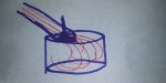
Thanks for your input, 'sid. I figured tge bend would be best for all of the obvious reasons but then I saw a diagram of an angled straight shot pipe to do with high performance stuff and it argued that the vast majority of flow would indeed heavily favor one side but that in turn would create swirl while packing the cylinder. It was enough to make me ask for a second opinion as I had tossed it around in my imagination while running simulations in my head (full top notch flow bench and high dollar engine simulation up there lol). I will sketch out a quick and dirty diagram showing the theory represented bt the straight shot pipe.

That's it! I will convert it to a rotary valve system! Ha

The drawing was just to compare intake ports. The exhaust will be high roof and tall and gentle bend short side.

Thanks again for your input.
 

Attachments

  • 20200629_031549.jpg
    20200629_031549.jpg
    154.1 KB · Views: 1
Messages
143
Reaction score
10
I like your idea of polishing the combustion chamber, piston and valve faces to ward off carbon deposits!

I "gasket match" the complete intake tract on any motor I tear down (because I can and want to) and every one big and small just seems smoother and happier to me. I leave a (perpendicular) 400 grit finish on small engines and usually a little coarser for automotive, moreso when they're carbureted.

For the exhaust side I still leave a sanded finish but pretty smooth (1500/2000 grit) because the "boundary layer" adds "lubrication" of sorts, 'sids comparison to saran wrap (sticky) is brilliant!

On the intake we know we want smooth, laminar flow across the ports which makes anti reversion difficult but not impossible... a proper "tuned" length of intake tract already has it build in by design. Reversion is in essence the sound wave travelling back and forth from one end to the other, "tuned" intakes (and exhausts for that matter - more on that coming up) have long, complicated equations that come into play so that sound wave will bounce off the valve right when it fully closes as to speed up the air down the tract while not disrupting the airflow into the chamber and is calculated in "waves" (1st wave 2nd wave ect.) based on the length but that's far too complicated for anything less that a full out purpose built racing engine!

The exhaust on the other hand works on the same principles but the goal is to have the wave revert off the head JUST before it opens as it will help draw the gasses out quicker (exhaust "scavenging") which helps draw in a little extra fuel charge during valve overlap. Anti-reversion (into the cylinder) on the exhaust is easy, make sure the exhaust port exit mouth on the head is a little smaller than your flange and pipe and that's it! The sound wave will bounce off of it instead of getting to the valve :2guns:

I for one will be following along because I think you're on to a cool experiment that you've put alot of time and thought into, bravo! :wai:

Hi Brianator, thanks for your input!

I like your idea of polishing the combustion chamber, piston and valve faces to ward off carbon deposits!

Thanks :)

I "gasket match" the complete intake tract on any motor I tear down (because I can and want to) and every one big and small just seems smoother and happier to me. I leave a (perpendicular) 400 grit finish on small engines and usually a little coarser for automotive, moreso when they're carbureted.

For the exhaust side I still leave a sanded finish but pretty smooth (1500/2000 grit) because the "boundary layer" adds "lubrication" of sorts, 'sids comparison to saran wrap (sticky) is brilliant!

Thanks for the info.

And I think 'sid's comparison was brilliant too.

On the intake we know we want smooth, laminar flow across the ports which makes anti reversion difficult but not impossible... a proper "tuned" length of intake tract already has it build in by design. Reversion is in essence the sound wave travelling back and forth from one end to the other, "tuned" intakes (and exhausts for that matter - more on that coming up) have long, complicated equations that come into play so that sound wave will bounce off the valve right when it fully closes as to speed up the air down the tract while not disrupting the airflow into the chamber and is calculated in "waves" (1st wave 2nd wave ect.) based on the length but that's far too complicated for anything less that a full out purpose built racing engine!

I was thinking about tatooing a tramp stamp on the valve bowl that reads "entrance only, no exit!".

Plan B is actually doing a long ugly tuned runner pipe with all the nerd math calculated out and build on of them fancy tuned pipes. Actually I have been doing it since about about 1996 when I had a turbocharged 2.2L Chrysler that came with a stock tuned pipe and plenum on it. Well that and my dad had been doing it for decades by that time and I asked him about the design and handed down his knowledge to me about tuned intakes (and exhaust) and away I went. There are a few more things that you can do to help prevent reversion that I might try. It's all about knowing what you need, what you want, knowing the limits and then making the best compromises. We will have to see how it unfolds. Thanks for the input though :)

The exhaust on the other hand works on the same principles but the goal is to have the wave revert off the head JUST before it opens as it will help draw the gasses out quicker (exhaust "scavenging") which helps draw in a little extra fuel charge during valve overlap. Anti-reversion (into the cylinder) on the exhaust is easy, make sure the exhaust port exit mouth on the head is a little smaller than your flange and pipe and that's it! The sound wave will bounce off of it instead of getting to the valve :2guns:

Very nice. Thanks :) I love a well scavenged engine. It just makes everything run better, cooler and more EFFICIENT! I will for sure be trying to dial in the exhaust to promote scavenging fo' sho' lol

I for one will be following along because I think you're on to a cool experiment that you've put alot of time and thought into, bravo! :wai:

Sweet! Thanks! I look forward to more input and comments from ya!
 

landuse

Moderator
Staff member
Messages
18,777
Reaction score
559
Location
Pietermaritzburg, South Africa
I know some people might hate on me for this, but I skip walls of text, even if it is spaced and paragraphed well. I just don't have the time to read a novel.

You have some good guys helping you though, so you should be fine.

And Poboy has been gone for a while (as Poboy anyway). Were you a lurker on the forum before you joined? :D
 
Messages
143
Reaction score
10
Ok, so from the beginning of thinking about tightening the ports up on this engine I have been trying to keep in mind something that I don't know if many people think about or realize about these little engine with "Hemi" heads and that is that the short side radius bend (the flat, wider portion making it a "D" port) is not actually the "port floor" as others online say it is. Part of it is part of the port floor... kinda, but part of it is the port wall too. Now this doesn't matter unless your the only fool (hence my name lol) in the world trying to tighten up and alter the ports at the same time on one of these unique engines. Other "D" shaped ports the flat wide area is the short radius side AND the port floor.

If you look at the the engine sitting level you will obviously notice that the head is angled in relation to the mounting surface. If you take off the intake and look at the intake (exhaust port is similar) port the "D" is angled with the head making the flat side of the port both part of the floor and wall at the same time. Now what I have to do is figure out how to tighten the port up while increasing laminar flow but still taking advantage of the short radius flat curve (a flatter/widder short turn radius helps to bend the air/fuel mixture flow down into the valve seat instead of the flow from the short side continuing to flow straight into the more gradual flow of the long side radius bend flow and screwing everything up).

So, I am trying to figure out the proper inlet placement, angle and how to create high CFM flow with high velocity but still take advantage of the "D" port when the short side radius is both the port floor and port wall. I am trying to design a biased side, vigh velocity, swirl enducing, nice CFM producing tunnel with a crooked "D" port. Lol

To further understand the design nightmare you have to consider that you have a valve guide screwing everything up so you have to bias (build one side of the port wider) the side towards the top right side of the short side radius because there is more material there to get the most gain from stock. In addition, you have to build one side of the port to flow slightly better than the other to induce swirl but in a way that the balance of de-compression through the valve seat is equalized. With all of that you have to decide on a taper, where the choke point will be to optimize velocity, place a shear to reintroduce fuel from the "V" shaped port floor (or floorS) without upsetting laminar flow and building a gradual slope for the short radius without cancelling out either the high flow or slow, offset swirl inducing slower flow.

Any suggestions? Lol

---------- Post added at 05:20 AM ---------- Previous post was at 05:07 AM ----------

I know some people might hate on me for this, but I skip walls of text, even if it is spaced and paragraphed well. I just don't have the time to read a novel.

You have some good guys helping you though, so you should be fine.

And Poboy has been gone for a while (as Poboy anyway). Were you a lurker on the forum before you joined? :D

Yeah, a lot of people skip big walls of text. I do the same thing unless I'm interested in the subject or build. It depends upon how the character of the person's writing though also. Yeah, I was a lurker. I read constantly so I am a lurker on many different forums on dozens of interests and subjects as well as an avid reader of patents, research and science papers, technical discussion chats, etc. I am mostely in search of learning and discovering new information. I tend not to actually interact much. I have here and there for a while but it gets old dealing with certain types of people so I just go about my business and move on. We will see how it goes. But I have been reading the forum here for years... Not always consistent, but when I have a build I want info on or looking for what others have done in similar situations I look on here as well as a bunch of others. I usually just keep to myself though. This is probably the type of wall of text that will keep you from reading lol
 

vpd66

Active member
Messages
198
Reaction score
57
Location
Wisconsin
I don't know if you have ever read or seen this book but it is exactly about what your trying to do. It covers how to modify, model, and test port modifications and it is very budget minded. You are working on a very simple single cylinder engine and you should easily be able to apply the techniques and theories covered in this book. I've done some of this testing back in my days of kart racing back in the 90s on 5hp flat head Briggs engines and its surprising how little things make a big difference and things that seem obvious really do nothing. Without a way to test your mods its really shooting in the dark. Also anyone that has spent any time on these engines are most likely racers and tend to keep secrets too themselves. The book is called "Practical Gas Flow" by John Dalton. I have a copy of this book that is copyrighted 1989 and I see there is an updated version dated 2001. https://i.ebayimg.com/images/g/jjMAAOSw7ple7fRX/s-l640.jpg

---------- Post added at 01:05 PM ---------- Previous post was at 12:55 PM ----------

The one modification that will give you the most bang for the buck in the torque department is compression. Up the compression has high has you can and research a fuel that can support it. Hint Hint E85. I call it the poor mans racing fuel. It has the octane rating of around 110 and you should be able to run 12-13/1 compression on it easy. Also engines run much cooler on too. I've built circle track stock car engines and ran them on E85 and we had to install thermostats in the engines to get them up to operating temperature.
 
Messages
143
Reaction score
10
I don't know if you have ever read or seen this book but it is exactly about what your trying to do. It covers how to modify, model, and test port modifications and it is very budget minded. You are working on a very simple single cylinder engine and you should easily be able to apply the techniques and theories covered in this book. I've done some of this testing back in my days of kart racing back in the 90s on 5hp flat head Briggs engines and its surprising how little things make a big difference and things that seem obvious really do nothing. Without a way to test your mods its really shooting in the dark. Also anyone that has spent any time on these engines are most likely racers and tend to keep secrets too themselves. The book is called "Practical Gas Flow" by John Dalton. I have a copy of this book that is copyrighted 1989 and I see there is an updated version dated 2001. https://i.ebayimg.com/images/g/jjMAAOSw7ple7fRX/s-l640.jpg


---------- Post added at 01:05 PM ---------- Previous post was at 12:55 PM ----------

The one modification that will give you the most bang for the buck in the torque department is compression. Up the compression has high has you can and research a fuel that can support it. Hint Hint E85. I call it the poor mans racing fuel. It has the octane rating of around 110 and you should be able to run 12-13/1 compression on it easy. Also engines run much cooler on too. I've built circle track stock car engines and ran them on E85 and we had to install thermostats in the engines to get them up to operating temperature.

I don't know if you have ever read or seen this book but it is exactly about what your trying to do. It covers how to modify, model, and test port modifications and it is very budget minded.

I don't think that I have read that book but I have read other stuff by John Dalton. Good stuff. Thanks for the info.

its surprising how little things make a big difference and things that seem obvious really do nothing

Ha! Isn't that the truth! Lol

The one modification that will give you the most bang for the buck in the torque department is compression. Up the compression has high has you can and research a fuel that can support it. Hint Hint E85. I call it the poor mans racing fuel. It has the octane rating of around 110 and you should be able to run 12-13/1 compression on it easy. Also engines run much cooler on too. I've built circle track stock car engines and ran them on E85 and we had to install thermostats in the engines to get them up to operating temperature.

Thanks for the tip. I was experimenting with E85 earlier in the 2000's when it started becoming more available when I was deep into turbos. I will look into using it for the kart engine and what it would take in reguards to designing an appropriate fuel delivery system to offset the undesirable properties included with E85. I'm not sure if it would need special stuff for the application or not. Thanks though.

p.s.- was considering using an Aisin AMR300 as a supercharger along with E85 for a gokart build a while ago though. I have to keep my mind from wondering into crazy builds. Lol
 

mckutzy

Well-known member
Messages
8,353
Reaction score
108
Location
bc, canada
If were talking a 212... I wonder how much the higher CR will handle on these little motors...
Its already easy enough to strip a head bolt, how much more tighter will it need to keep past stock let alone 12:1+ CR.
 
Top