2017 - El Moto

Functional Artist

Well-known member
Messages
5,276
Reaction score
2,713
Location
Toledo, Ohio
Looks like you're gonna have a whole mess of room for bat trees.*


*An old friend used to say it that way! :D


Lost me for a minute there,

...what's a bat tree?

OK, I got cha


Yup, I was thinkin' that too :thumbsup:

For now, I have it set up to run @ 36V

So, I will probably use (3) of the 35AH batteries I already have (60 lbs.)

...then later, maybe, jump up to 48V

...by adding another battery (80 lbs.) & switching to a 48 V solenoid


...then if/when I can afford it

...to reduce weight & extend the run time

...maybe jump up to a 48V 47AH lithium Ion VOLT battery (45 lbs.)


So, ya

...we need lots of room down there


Plus, the more room we have to work with

...we can be more creative with component placement (to look kool)

...we can spread the components out more, to help reduce heat build up
 

Bbqjoe

Banned
Messages
3,455
Reaction score
64
Location
Location, Location
Just a thought, before it's too late.
What about making a bracket like a rear luggage rack, and mounting the motor above the rear tire?
That would leave more room for batteries and gizmos in the frame.
 

Functional Artist

Well-known member
Messages
5,276
Reaction score
2,713
Location
Toledo, Ohio
Just a thought, before it's too late.
What about making a bracket like a rear luggage rack, and mounting the motor above the rear tire?
That would leave more room for batteries and gizmos in the frame.

Now, your talkin' crazy :smiley_omg:

Too top heavy :ack2:

...a 40 lb. weight, up on a luggage would totally change the handling of the bike

Plus, that's where the Press goes :thumbsup:
 

Functional Artist

Well-known member
Messages
5,276
Reaction score
2,713
Location
Toledo, Ohio
We need to use a jack shaft type set up

... to help route the chain around the trailing arm


So, next lets discuss

...the jack shaft


Our jack shaft consists of

...a piece of 3/4" hardened steel axle shaft with key way & retainer ring grove (will cut to size)

...(2) pillow block bearings (for 3/4" shaft)

...I gonna (try to) use the 15 tooth sprocket I already have

...~1" piece of key stock

...maybe a washer or (2)

...& a retaining ring
 

Attachments

  • SAM_4715.jpg
    SAM_4715.jpg
    291.5 KB · Views: 3
  • SAM_4717.jpg
    SAM_4717.jpg
    246.6 KB · Views: 3
  • SAM_4706.jpg
    SAM_4706.jpg
    204.5 KB · Views: 2
  • SAM_4705.jpg
    SAM_4705.jpg
    204.8 KB · Views: 2
  • SAM_4603.jpg
    SAM_4603.jpg
    270.3 KB · Views: 2

Functional Artist

Well-known member
Messages
5,276
Reaction score
2,713
Location
Toledo, Ohio
Where did you get the hardened shaft w/keyway?

I'm glad you asked. :thumbsup:


It's out of a Craftsman riding lawnmower transaxle that I disassembled years ago

It took me a minute to find it

It was part of a homemade axle for a kart I built using a V8 Chevy car starter

I used the (2) axle pieces, mounted a pulley in between & spliced them together with a piece of pipe

It worked but, visibly flexed in the middle when pressure was added to the belt (I wouldn't recommend it)

It (the starter motor) only lasted a couple of "city" blocks :ack2:

http://www.diygokarts.com/vb/showthread.php?t=34016
 

Attachments

  • SAM_4719.jpg
    SAM_4719.jpg
    357 KB · Views: 3
  • SAM_4597.jpg
    SAM_4597.jpg
    259.9 KB · Views: 2
  • SAM_4595.jpg
    SAM_4595.jpg
    201.4 KB · Views: 1
  • SAM_4594.jpg
    SAM_4594.jpg
    432.9 KB · Views: 1
  • SAM_1336.jpg
    SAM_1336.jpg
    329.6 KB · Views: 5
  • SAM_1338.jpg
    SAM_1338.jpg
    246.8 KB · Views: 3
  • SAM_1339.jpg
    SAM_1339.jpg
    275.8 KB · Views: 4

Functional Artist

Well-known member
Messages
5,276
Reaction score
2,713
Location
Toledo, Ohio
If you'll notice, the motor mount hangs off the trailing arm by a couple of inches

It shouldn't be a problem

...but, I don't like it :ack2:

Thought about just cuttin' the extra off

...motor is rounded

...doesn't really help

NO, we want more support :thumbsup:

NOT less

...& I don't want to modify/damage the motor mount too much (if this plan don't work out)

I could add a plate under the motor mount (does not add much additional support)

...& I can't attach/support it just anywhere, because the trailing arm moves with the travel of the rear wheel, independent of the frame

:idea2:

how about extending the trailing arm a bit by adding a box to the front edge?

...that would look good & giv'er additional support :2guns:

https://www.youtube.com/watch?v=QvE4Ir8pxPk
 

Attachments

  • SAM_4739.jpg
    SAM_4739.jpg
    215.8 KB · Views: 3
  • SAM_4770.jpg
    SAM_4770.jpg
    294.6 KB · Views: 3

Functional Artist

Well-known member
Messages
5,276
Reaction score
2,713
Location
Toledo, Ohio

Attachments

  • SAM_4763.jpg
    SAM_4763.jpg
    304.6 KB · Views: 2
  • SAM_4753.jpg
    SAM_4753.jpg
    271.4 KB · Views: 2
  • SAM_4744.jpg
    SAM_4744.jpg
    245.4 KB · Views: 2
  • SAM_4740.jpg
    SAM_4740.jpg
    240.7 KB · Views: 2
  • SAM_4739.jpg
    SAM_4739.jpg
    215.8 KB · Views: 2
  • SAM_4770.jpg
    SAM_4770.jpg
    294.6 KB · Views: 2

Functional Artist

Well-known member
Messages
5,276
Reaction score
2,713
Location
Toledo, Ohio
Standard pillow block bearings won't work

...foot print is too big

...sticks out into rear tire area

Did some research,

I found these threaded base pillow block bearings, which don't have the bolt down flanges

Yup!, that should work :thumbsup:
 

Attachments

  • SAM_4707.jpg
    SAM_4707.jpg
    370.5 KB · Views: 2
  • SAM_4706.jpg
    SAM_4706.jpg
    204.5 KB · Views: 2
  • SAM_4830.jpg
    SAM_4830.jpg
    247.8 KB · Views: 2
  • SAM_4836.jpg
    SAM_4836.jpg
    245.8 KB · Views: 3

Functional Artist

Well-known member
Messages
5,276
Reaction score
2,713
Location
Toledo, Ohio
Now, that we know where the jack shaft needs to be mounted

Next, was to get it mounted to it's plate

After disassembling, I used it as a guide to get everything lined up & mounted on to the bike

...using the jackshaft plate as a template, I drilled the holes into the trailing arm

...then, I used the jack shaft plate & trailing arm as a template to drill the holes into the motor mount plate

...then, I lined up the motor with the rear sprocket & jackshaft sprocket & drilled holes into the motor mount


https://www.youtube.com/watch?v=P3EOoFsOFu4
 

Attachments

  • SAM_4850.jpg
    SAM_4850.jpg
    343.1 KB · Views: 3
  • SAM_4846.jpg
    SAM_4846.jpg
    365.2 KB · Views: 3
  • SAM_4837.jpg
    SAM_4837.jpg
    244.1 KB · Views: 3

Functional Artist

Well-known member
Messages
5,276
Reaction score
2,713
Location
Toledo, Ohio
Wow!

That was tedious

...gettin' all that stuff lined up & drilled

I had to unhook the shocks

...drop the rear wheel

...lay the bike on its side

...all while not breakin' or scrachin' nuttin' :thumbsup:

And the whole time, worrying :huh:

...is the jack shaft lined up?

...or is the motor lined up?

...or is everything lined up with the rear wheel?

...or did I forget or leave out any important detail?

Because, the way this is set up, it would be a nightmare to adjust anything


But, everything seems to line up OK :wai:

...the trailing arm is solidly sandwiched between the motor & jack shaft

...the chain seems to run smoothly

...& looks kuhl (my new way to sat kool - thanks Sid)


...I would call it "mechanical art" :2guns:

https://www.youtube.com/watch?v=WFKgGyDU0IY
 

Attachments

  • SAM_4867.jpg
    SAM_4867.jpg
    289.4 KB · Views: 2
  • SAM_4865.jpg
    SAM_4865.jpg
    348.5 KB · Views: 2
  • SAM_4873.jpg
    SAM_4873.jpg
    230.1 KB · Views: 2
  • SAM_4877.jpg
    SAM_4877.jpg
    317.7 KB · Views: 3

Functional Artist

Well-known member
Messages
5,276
Reaction score
2,713
Location
Toledo, Ohio
Next...component placement

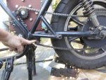
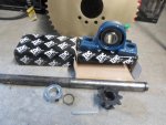
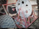
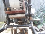
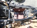
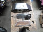
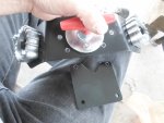
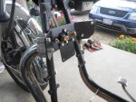
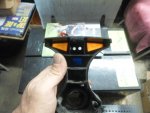
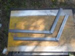
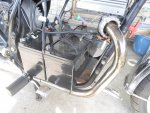
The first pic is the breast plate, the thumb throttle bracket & the speed controller bracket

The breast plate is where

...the exhaust pipes will originate

...the main power cut off will be mounted

...& where our solenoid will mount

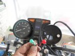
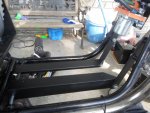
The thumb throttle mount is where

...the thumb throttle will be mounted & the bracket that holds the stock throttle cable

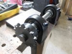
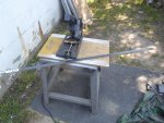
Then is the speed controller mount

...that's where we'll start, the speed controller (the brain)

...it's the next biggest piece after the motor & bat trees (my new way of sayin' batteries - Thanks BBQ JO) :thumbsup:

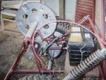
...it gets hot so, ample kuhling is best

...but, it's kinda delicate & all the main electrical connections go there so, it's gotta be protected too

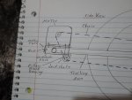
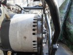
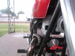
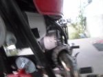
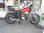
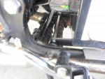
Let's see if we can tuck it up under the gas tank (it will be protected & have lots of air flow)

...it'll look kuhl too with the shinny lines of the controller & the kuhler (heat sink)

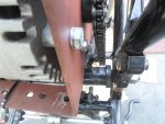
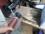
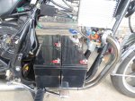
I used a piece of 3/16" steel to make a mounting bracket

...it bolts to the speed controller/heat sink on one end

...& on the other, it bolts to where the coil for the old gas engine bolted to the frame of the bike


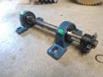
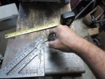
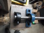
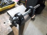
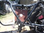
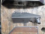
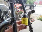
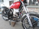
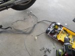
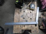
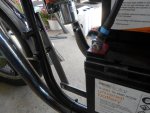
Next, is the throttle bracket

...simple piece of 3/16" angle steel

...with a piece of 7/8" od. water pipe welded on

...it will be mounted under the tank also

...where the upper gas engine mount used to be bolted to the frame


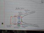
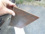
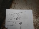
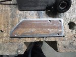
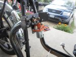
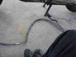
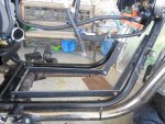
The breast plate is a piece of 1/8" x 3" steel

...with a couple of custom bends

...it mounts just inside the (2) front frame rails


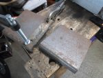
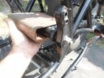
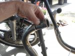
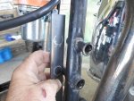
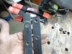
After cuttin' the exhaust pipes off

...I used a dremel to smooth the edges

...then coated the edges with liquid rubber (didn't want metal to metal squeakin')


I bolted the stock exhaust flanges to the breast plate

...& coated the inside of both flanges with liquid rubber


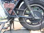
When I mounted it on the bike

...I tucked the pipe ends into the flanges & secured them with screws up thru the bottom

That should do it! :2guns:

https://www.youtube.com/watch?v=FYukp1LCrMQ
 

Attachments

  • SAM_4940.jpg
    SAM_4940.jpg
    274.5 KB · Views: 2
  • SAM_4941.jpg
    SAM_4941.jpg
    231.3 KB · Views: 3
  • SAM_4939.jpg
    SAM_4939.jpg
    320.3 KB · Views: 3
  • SAM_4938.jpg
    SAM_4938.jpg
    253.8 KB · Views: 3
  • SAM_4982.jpg
    SAM_4982.jpg
    244.4 KB · Views: 4
  • SAM_4980.jpg
    SAM_4980.jpg
    307.8 KB · Views: 4
  • SAM_4973.jpg
    SAM_4973.jpg
    250.7 KB · Views: 3
  • SAM_4963.jpg
    SAM_4963.jpg
    314.2 KB · Views: 3
  • SAM_4954.jpg
    SAM_4954.jpg
    222.8 KB · Views: 3
  • SAM_4988.jpg
    SAM_4988.jpg
    345.9 KB · Views: 5

Functional Artist

Well-known member
Messages
5,276
Reaction score
2,713
Location
Toledo, Ohio
Now, all the custom mounting brackets are fabricated & sealed up

Lets get 'em on the bike

First, I mounted the speed controller on to it's bracket then on the bike

...mounting was simple

...but, when bolted down tight, a flange on the heat sink stuck out a bit & the tank would not clear (it seemed to clear OK in pre fitting)

...so, I had to trim the flange off

Yup, it clears nicely now :thumbsup:


Next, was the breast plate

...after installing the power cut off switch & bolting the exhaust flanges on

...we need to get it mounted to the front frame rails, under the fuel tank

...I didn't want to drill into the frame so, I used (2) rubber coated hydraulic hose mounting straps

...they wrap around each of the frame bars & hold the breast plate in place nicely with a couple of nuts & bolts

Once mounted, I added the solenoid & bracket


Next, was the thumb throttle bracket

...pretty simple mounting also, used existing holes (was for the engine coil)

...tucked right up under the tank right behind the speed controller

...pretty close to where the carburetor's used to be

...so, I can use the stock throttle handle & cable for an authentic feel
 

Attachments

  • SAM_4984.jpg
    SAM_4984.jpg
    243.7 KB · Views: 2
  • SAM_5001.jpg
    SAM_5001.jpg
    247.8 KB · Views: 1
  • SAM_5000.jpg
    SAM_5000.jpg
    294.3 KB · Views: 6
  • SAM_4993.jpg
    SAM_4993.jpg
    291.5 KB · Views: 2
  • SAM_4988.jpg
    SAM_4988.jpg
    345.9 KB · Views: 1
  • SAM_4987.jpg
    SAM_4987.jpg
    347 KB · Views: 1
  • SAM_5002.jpg
    SAM_5002.jpg
    207.5 KB · Views: 1

Functional Artist

Well-known member
Messages
5,276
Reaction score
2,713
Location
Toledo, Ohio
Next, is wiring our propulsion system

The wiring harness I made for El Dingo is like 5' long :ack2:

So, were gonna' have to make some adjustments

...& since the motorcycle already has a 12V electrical system

...I can eliminate the 12V circuit I added to operate the control box cooling fan


Before I go chopping this harness up


lets be kinda methodical about this

...start at the speed controller

...install cable J1 & J2 by screwing each connector into it's designated location on the speed controller


Then start running the different wires to where they go

...throttle input wire goes to the thumb throttle

...brake signal wire goes to brake switch area (have to mount a separate switch)

...indicator lights (red & green LED's) go to dash area

...solenoid signal circuit wires go to solenoid on the breast plate

...thermosister wires goes to the (back side) motor area

...& finally, wiring an on/off switch for the controller
 

Attachments

  • SAM_5117.jpg
    SAM_5117.jpg
    439.6 KB · Views: 1
  • SAM_5118.jpg
    SAM_5118.jpg
    397.8 KB · Views: 1
  • SAM_5119.jpg
    SAM_5119.jpg
    437.3 KB · Views: 1

Functional Artist

Well-known member
Messages
5,276
Reaction score
2,713
Location
Toledo, Ohio
I added a return spring to ensure a good throttle return response (very important) :cornut:


Next,

I had to take the dash apart to install the (2) LED lights

...they give us the controller info (tell us when it's on/off & diagnostic stuff)


There is a couple of places I could of put them

...sticking out of the top

...where the neutral indicator light was

...or on a separate plate


Right at the top, of the dash was a space, between the turn signal indicator lights, that said Kawasaki

...lets put 'em there

...easily seen, nice & prominent but, not gaudy or out of place :thumbsup:

Also,

...removed the gas engine RPM gauge (don't need it no more)

...replaced it with a 36V charge meter (tells us the charge level of the bat tree pack

* I ordered it last year with other stuff for El Dingo (diagram said there was a charge indicator wire) but, when I got it, it was huge & wouldn't of looked right on the kart so it went on the shelf

I was pleasantly, surprised when, it just happened to fit right in

...it kinda matched the speedometer

...& bolted into the same mounting holes as the old RPM gauge :2guns:

https://www.youtube.com/watch?v=brv_eddtI0I
 

Attachments

  • SAM_5078.jpg
    SAM_5078.jpg
    215.8 KB · Views: 1
  • SAM_5077.jpg
    SAM_5077.jpg
    228.5 KB · Views: 1
  • SAM_5076.jpg
    SAM_5076.jpg
    181.6 KB · Views: 1

Functional Artist

Well-known member
Messages
5,276
Reaction score
2,713
Location
Toledo, Ohio
Now, for the bat trees :thumbsup:

The original plan was to stack the (3) 35AH bat trees "pyramid" style for the 36V for the propulsion system

...& use a separate 12V 12AH bat tree to power the 12V system on the motorcycle (head & brake lights, turn signals & horn)

Then later

...add another bat tree (to step up the propulsion system to 48V)

...add a voltage converter to power the 12V system

But, I was thinkin'

...why not just set it up for (4) 35AH bat trees, now

...(3) for 36V & (1) for 12V

Then later,

...switchin' to 48V will only be some cable reconfiguration & a 48V solenoid


Yup! that's what were gonna do :2guns:
 

Attachments

  • SAM_5160.jpg
    SAM_5160.jpg
    363.8 KB · Views: 3
  • SAM_5238.jpg
    SAM_5238.jpg
    401.8 KB · Views: 3

Functional Artist

Well-known member
Messages
5,276
Reaction score
2,713
Location
Toledo, Ohio
Just set the bat trees

...on a piece of 1/4" plywood

...that was sittin' right on the frame rails

...for placement/measurement purposes

But, the gas engine (the main weight inside the frame) wasn't just sittin' on the frame rails

It was kinda suspended above the frame rails & supported on the sides

So, lets NOT just sit the bat trees right on the frame rails

Actually, lookin' at it, contemplating, evaluating the situation

I think, I came up with a simple but, kuhl solution :idea2:

I can use a couple of pieces of 1/4" x 1" steel

...that attach to the lower rear gas engine mount

...run along/behind the frame

...to junction with a couple of pieces of 1/4" x 1" steel coming down from where the front gas engine mounts were bolted to the frame

...even reused the stock bolts (from removing the engine)
 

Attachments

  • SAM_5162.jpg
    SAM_5162.jpg
    185.4 KB · Views: 1
  • SAM_5164.jpg
    SAM_5164.jpg
    431.3 KB · Views: 1
  • SAM_5169.jpg
    SAM_5169.jpg
    359.8 KB · Views: 1
  • SAM_5170.jpg
    SAM_5170.jpg
    239.2 KB · Views: 1
  • SAM_5178.jpg
    SAM_5178.jpg
    275.4 KB · Views: 1
  • SAM_5174.jpg
    SAM_5174.jpg
    189 KB · Views: 1
  • SAM_5188.jpg
    SAM_5188.jpg
    274.6 KB · Views: 2
  • SAM_5203.jpg
    SAM_5203.jpg
    371.1 KB · Views: 2

Functional Artist

Well-known member
Messages
5,276
Reaction score
2,713
Location
Toledo, Ohio
Well the plan was simple

...the execution was a bit more involved


The first set of bottom rails (1/4" x 1")

...were a bit too short

The second set (1/4" x 2")

...were a bit too tall

...plus I would of had to bolt or weld the battery tray down to secure it

So, I was thinkin'

...why not just use pieces of angle steel

...it would provide the up right rails with flat plate tops built right in

So, the

...third set was pieces of (3/16" x 1 3/4") angle steel


Yup! they were just right :thumbsup:


It just took (4) hours to get it right :ack2:


* Bonus: I'm getting a good work out, musclin' these bat trees in & out a 100 times


https://www.youtube.com/watch?v=MvyuobdxOwA
 

Attachments

  • SAM_5208.jpg
    SAM_5208.jpg
    251 KB · Views: 1
  • SAM_5211.jpg
    SAM_5211.jpg
    379.6 KB · Views: 1
  • SAM_5213.jpg
    SAM_5213.jpg
    538.1 KB · Views: 1
  • SAM_5233.jpg
    SAM_5233.jpg
    265.7 KB · Views: 1
  • SAM_5236.jpg
    SAM_5236.jpg
    280.4 KB · Views: 3
Top