'wittle 'wesistor (Mini Jeep)

Functional Artist

Well-known member
Messages
4,406
Reaction score
1,686
Location
Toledo, Ohio
Another feature, that I added to the pedal assembly, was a micro-switch to activate the brake lights :thumbsup:
SAM_6971 (1).JPG
...& when activated, it also de-activates the motor/traction system
(so, the system cannot be trying to "go" & "stop" at the same time)

* These little switches can be wired/configured as Normally Open & Momentarily Closed when activated (like for this application)
...or Normally Closed & Momentarily Open (when activated) depending on which (2) of the (3) terminals are connected &/or used

* Also, notice this switch is rated for
...0.3A at 250VDC
...0.6A at 125VDC

Going by this "scale" (I'm thinking/IMO) it "should" be able to handle (safely break the current, without damaging itself) ~1.2A at 60VDC
...& then, maybe up to ~1.5A if/when used on a 48VDC system (like this vehicle will have)

** The brake light & running light circuits are powered by 48VDC (full pack voltage)
...so, I'm thinking about using (4) 12V LED's trailer marker lights (wired in-series) for the brake lights
...& (4) separate 12V LED's (wired in-series) for the running lights
(just mount (2) of each of them, in each one of the taillight housings)

The 3/4" round 12V LED trailer marker lights, that I plan to use, seem to draw ~0.05A
...& (4) of them, powered simultaneously, should only draw ~0.2A

So, all components in the Brake light circuit, should be able to handle at least 0.5A (AKA 1/2A)
...which is ~3 times higher than the switches (theoretical) rating :cheers2:
 

Functional Artist

Well-known member
Messages
4,406
Reaction score
1,686
Location
Toledo, Ohio
While were talking about switches, let's look at what other switches we will need.

The plan is to use (2) 48V 1,000W MY-1020 motors (~1.2HP ea. so, ~ 2.5HP total)
...& (2) YK-31 Speed Controllers (with Reverse)

Here is the wiring definition for a YK-31 speed controller

1. Power: Thick Red wire (Batt +) & Thick Black wire (Batt -) --- Connect to Batt Pack
2. Motor: Thick Yellow wire & Thick Blue wire --- Connect to Motor
3. Lock (KSI): Thin Red wire & Thin Blue wire --- Connect to Power Switch
4. Throttle: Thin Red (+5V) & Thin Black wire (-) & Thin Green wire (signal) --- Connect to Throttle
5. Charger: Thin Red wire (+) & Thin Black wire (-) --- Connect to Battery Charge Port
6. Brake: Thin Green wire & Thin Black wire --- Connect to Brake Switch
7. Batt (+): Thin Red wire (+) & Thin Black wire (-) --- Connect to (running) Lights or Voltage Meter
8. Brake Lamp: Thin Red wire (+) & Thin Green wire (-) --- Connect to Brake Lamp
9. Reverse: Thin Yellow wire (+) & Thin Black wire (-) --- Connect to Reverse Switch
10. Batt (+): Thin Red wire (+) --- (Spare)

The functions we need to be able to control ("switch" On or Off) are:
... #3 Lock (a simple On/Off switch that turns the SC On or Off)
...#6 Brake (a simple On/Off switch that activates the brake functions (power cut-off & brake light)
...& #9 Reverse (a simple On/Off switch that activates the reverse function)

FYI, all of these functions are/operate at pack voltage (48V in this case)
...& they are all "signal" circuits

So, because they are just sending signals (not carrying a lot of current "powering" a component)
...they (usually) don't carry much of (if any) "load"

So, the switches (to control these functions) need to be able to handle 48VDC
...but, (remember) they don't have to "handle" (or be able to deal with) hardly any "load" (usually less than ~1/2A)

* So, "my" thinking on this is:
If the amount of current flowing thru a circuit, can produce a visible arc
...then, there "could" be enough current available/flowing, to be harmful to the contacts of an under-rated switch
But,
If the amount of current flowing thru a circuit is not sufficient to produce a visible arc
...then, there isn't really enough current flowing, to be harmful to the contacts of most any switch.

But,
I have to add:
This is just "my" opinion
...& it is BEST to USE PROPERLY RATES SWITCHES :cheers2:
 
Last edited:

Functional Artist

Well-known member
Messages
4,406
Reaction score
1,686
Location
Toledo, Ohio
So what are you doing to handle the load amperage? Is it an independent dedicated fused circuit(s)?
Hey Mad,
That statement "they don't have to "handle" (or be able to deal with) hardly any "load" (usually less than ~1/2A)"
...only applies to the switches for connections #3, #6 & #9
...because they are just signal circuits.

There will be a 48V 50A Circuit Breaker (on the positive (+) cable) between the batt pack & connection #1.
...1.) Power: Thick Red wire (Batt +) & Thick Black wire (Batt -) --- Connect to Batt Pack)
 

madprofessor

"Loose Cannon Creations"
Messages
2,899
Reaction score
888
Location
Jacksonville, Florida
So several signal (negligible amps) circuits are run from the source power? Don't you want to separate them with a low amps fuse or breaker to isolate for trouble-shooting, as opposed to just letting them be ancillary off of the main?
 

Functional Artist

Well-known member
Messages
4,406
Reaction score
1,686
Location
Toledo, Ohio
So several signal (negligible amps) circuits are run from the source power? Don't you want to separate them with a low amps fuse or breaker to isolate for trouble-shooting, as opposed to just letting them be ancillary off of the main?
If I understand your question correctly
...the main power goes into the Speed Controller via. the Circuit Breaker
...& then, all circuits are isolated, inside of the Speed Controller

Signal circuits don't usually need a fuse
...because they aren't carrying much (if any) current (other than a direct short, a fuse wouldn't/couldn't really do anything, in this situation)
...but, if one was added, it probably wouldn't hurt anything (just make everything more complicated)
 

Functional Artist

Well-known member
Messages
4,406
Reaction score
1,686
Location
Toledo, Ohio
Now, lets discuss BMS's

All BMS'a are Battery Monitoring Systems
...& they all connected to (each cell)
...& monitor each cell, individually

There are (2) main types of BMS's
...Passive (Battery Monitoring System)
...Active (Battery Managment System)

A Passive BMS is just a monitoring system
...that "passes" the information to the user
...& the user must make the decisions
...& then, "act" upon them decisions (if & when, necessary)

An Active BMS monitors the pack
...but also, has the ability to "act"
...& "switch" things "On &/or Off (if & when, it deems it necessary)

Like:
Under-Voltage protection (Low Voltage cut-off)
Over-Voltage Protection (High Voltage cut-off)
Over Current Protection (High Amp draw cut-off)
Temperature Protection (High or low temp cut-off)
Balance Protection (Individual Cell Balancing)


So, whether to use a BMS is not the question
IMO if your using a Lithium battery you should monitor it (at the very least) :thumbsup:

The question is, does the specific battery pack being used, need (or would it be best to use) an Active BMS or a Passive BMS?
 

Functional Artist

Well-known member
Messages
4,406
Reaction score
1,686
Location
Toledo, Ohio
OK
Before making any decisions about a BMS, let's look into the requirements of
...a 48V system
...& 48V Battery packs

For simplicity's sake, let's take look at this, from an old 48V electric golf cart, point of view ;)

Hey Denny, this stuff may be right up your alley &/so, please correct &/or clarify "if" necessary :thumbsup:

An older 48V golf cart was usually powered by either
...(4) 12V Lead Acid Deep Cycle batteries
... or (8) 6V Lead Acid Deep Cycle batteries

The voltage specs of an average 12V lead Acid battery is
...Low: ~10.5V
...Nom: ~12V
...& High: ~13.5V
&/so
The voltage specs of (4) 12V Lead Acid batteries would be
...Low: ~41V
...Nom: ~48V
...& High: ~54V

So, as far as a BMS (Battery Management System)

Under-Voltage Protection
The Under-Voltage protection was provided by the Speed Controller

Which for a 48V cart, the Low-Voltage cut-off was usually pre-set to ~41V
...& "if" the battery pack dropped below ~41V it would automatically "shut the system down" to help protect the batt pack from over-discharging

Over-Voltage Protection
The Over-Voltage Protection was provided by the Battery Charger
Which was in control, of re-charging the batteries (& the High-Voltage cut-off)
...& would automatically shut the charger off, when the pack was re-charged up, to the pre-set limit, to keep the batt pack from over-charging

Over Current Protection (High Amp draw cut-off)
The Over Current Protection was provided by the Speed Controller (sometimes) 🤔

Temperature Protection (High or low temp cut-off)
They usually didn't have or provide any temperature monitoring or cut-off type abilities

Balance Protection (Individual Cell Balancing)
The monitoring or balancing, of the individual cells (or even modules) was usually not provided
...or even "worried about" AFAIU
 

Denny

Canned Monster
Messages
8,447
Reaction score
4,684
Location
Mayberry, Indiana
48v golfkarts had 6, 8volt batteries. E-Z-GO and Club Car both used controllers with the brains for the chargers built into them. They just supplied the dc voltage. I had a way of outsmarting the battery chargers used to change 1 wire around. But it was 20 years ago and I’ve slept since then.
 

Functional Artist

Well-known member
Messages
4,406
Reaction score
1,686
Location
Toledo, Ohio
After all of that "yakking" about electronics, let's move on to the box that will house most of "that stuff".

I picked up a (4' x 8') sheet of 18G steel (I had it sheared (into 3 pieces) to make it easier to transport & work with)
...& it looks like I can get both (top & bottom) pieces of the battery box
...& also, both of the floorboard sections (front & rear)
...plus, a few of other parts, that we will need, like the fenders (inner & outer) out of it :thumbsup:
SAM_7063.JPG
Before "attacking" the sheet of steel, I designed/drew up a battery box
...& then, went back to the CAD (cardboard aided design)
SAM_7023.JPG
...& made a "life size model" of the bottom 1/2 of the battery box ;)

*To make sure that "it" would fit inside of the frame rails
...& also, be able to hold the battery module & most of the electronics :cheers2:
SAM_7026.JPG
 

Functional Artist

Well-known member
Messages
4,406
Reaction score
1,686
Location
Toledo, Ohio
Battery Box Bottom
I used the CAD template, to mark the steel
...& then, cut 'er out
SAM_7030.JPG
Next, I drew the lines where I needed to make the bends
...put 'er in the bender
...& bent 'er up

First, I bent the mating/bolting flanges
SAM_7079.JPG
...then, did the "long" side bends
SAM_7085 (1).JPG
...& then, the shorter sides (Notice the creative clamping method) ;)
SAM_7089.JPG
...& Ju'alla :devil2::innocent:
SAM_7095.JPG
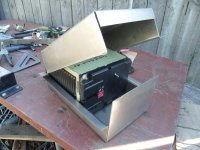
Test Fit the battery module (nice-n-snug)
SAM_7096.JPG
...& here is the area, where most of the electronics will be connected & "secured" :thumbsup:
SAM_7097.JPG
 
Top