
You are using an out of date browser. It may not display this or other websites correctly.
You should upgrade or use an alternative browser.
You should upgrade or use an alternative browser.
what kind of motor?
- Thread starter Fenrir
- Start date
- Status
- Not open for further replies.

Would a bicycle chain be strong enough to transfer the motor power to the axel ?
Thanks
No, definately not. They are designed for torque generated by leg power, and will not handle the torque from an engine. You will have to use at least a #35 chain

I agree..
MY1020s often come with a #25 chainsprocket, so one would assume that's good enough.
And I think up to a certain weight it will be.
I guess a 200kg kart is beyond that already, so I'd like to suggest something a bit bigger than that (like Paul said a #35 for example)
'sid
MY1020s often come with a #25 chainsprocket, so one would assume that's good enough.
And I think up to a certain weight it will be.
I guess a 200kg kart is beyond that already, so I'd like to suggest something a bit bigger than that (like Paul said a #35 for example)
'sid
Fenrir;308716]thanks i'll start looking for one
i don't really understand how you decide if the throttle is the correct one, is it the voltage that decides it ?
and i'm scared i'm gonna break the controller the motor says 27.4Amps but can the controller handle it ?

thanks
i don't really understand how you decide if the throttle is the correct one, is it the voltage that decides it ?
and i'm scared i'm gonna break the controller the motor says 27.4Amps but can the controller handle it ?
thanks
the controller is made to easily take 31Amps, so yes it will handle the motor currents.
the YK31c requires a 5V driven hall effect sensor returning 0-4V (zero to full throttle)
So, any e-bike twist throttle is good (get a cheap one.. the expensive ones aren't any better.. just more expensive)
any e-scooter thumb throttle will do too.
EV pedal throttles are a little trickier, some do not return more than 3V (and you won't reach top speed) and some do not return less than 1V (and the kart might be rolling)
Also they can be expensive (golf cart throttles for example or worse industrial cart ones)
If you find a throttle that's returning 0-5V instead 0-4, that's okay, you'll have a bit of play on the upper end (movement from 4-5V) where the motor is already at full speed,
but that's just a cosmetic thing..
the controller will still be okay with that.
If you tell me which type you intend to buy (twist, thumb, pedal)
I might find one for you.
'sid
the YK31c requires a 5V driven hall effect sensor returning 0-4V (zero to full throttle)
So, any e-bike twist throttle is good (get a cheap one.. the expensive ones aren't any better.. just more expensive)
any e-scooter thumb throttle will do too.
EV pedal throttles are a little trickier, some do not return more than 3V (and you won't reach top speed) and some do not return less than 1V (and the kart might be rolling)
Also they can be expensive (golf cart throttles for example or worse industrial cart ones)
If you find a throttle that's returning 0-5V instead 0-4, that's okay, you'll have a bit of play on the upper end (movement from 4-5V) where the motor is already at full speed,
but that's just a cosmetic thing..
the controller will still be okay with that.
If you tell me which type you intend to buy (twist, thumb, pedal)
I might find one for you.
'sid
a twist
i was thinking of this one :
http://www.ebay.com/itm/12V-24V-36V...969?pt=LH_DefaultDomain_0&hash=item19d7414f41
thanks
i was thinking of this one :
http://www.ebay.com/itm/12V-24V-36V...969?pt=LH_DefaultDomain_0&hash=item19d7414f41
thanks
that should work well.
'sid
'sid
lucky YOU!
the motor is okay, not the seller.. $560 ??
for a motor that's maybe 70€ around her?
You shouldn't bother
here we go, a my1050 is all I can find atm:
http://www.ebay.fr/itm/E-Scooter-El...=DE_Sport_Elektro_Scooter&hash=item25896fac76
I think they ship to Belgium too:
http://tncscooters.com/index.php?route=product/product&path=52_55&product_id=59
(IIRC that's where Flurky123 got his)
'sid
the motor is okay, not the seller.. $560 ??
for a motor that's maybe 70€ around her?
You shouldn't bother
here we go, a my1050 is all I can find atm:
http://www.ebay.fr/itm/E-Scooter-El...=DE_Sport_Elektro_Scooter&hash=item25896fac76
I think they ship to Belgium too:
http://tncscooters.com/index.php?route=product/product&path=52_55&product_id=59
(IIRC that's where Flurky123 got his)
'sid
Hello,
I'll get into this conversation right now
I still remember the time when I knew nothing , this time around I have learned a lot about Electric gokarts.
At first: Itsid, I didn't know you have been in Belgium for a while. And what you said about the beer isn't true. Have you tried Jupiler, Leffe, Primus, Maes,... Those are great beers.
To get to topic: Yes tncscooters is a very nice company. They were really helpfull (they responded to mails within 3 days). The delivery to Belgium was quite expensive (65 dollars) and when it arrived I had to pay another €38 (I guess for customs). But the main reason for me to shop in New York was that I could order everything I need in one shipping.
For the rest I give the advice to pick a controller, off which you have a wiring diagram. When I put things together, I had to double check all connections. Also take in mind that your system doesn't work, if not all of the needed connections are in place.
Connections you definitely need:
-Power lock
-Battery connection
-Motor connection
-Throttle (Derailleur) connection
-Brake connention (which comes with Derailleur)
And make sure you buy some connectors aswell. I don't know if it's a unit you can find a lot in Europe.
And €70 for the motor is still a high number. I got mine (1000W/36V) for +-€90.
Flurky123
I'll get into this conversation right now
I still remember the time when I knew nothing
, this time around I have learned a lot about Electric gokarts.At first: Itsid, I didn't know you have been in Belgium for a while. And what you said about the beer isn't true. Have you tried Jupiler, Leffe, Primus, Maes,... Those are great beers.
To get to topic: Yes tncscooters is a very nice company. They were really helpfull (they responded to mails within 3 days). The delivery to Belgium was quite expensive (65 dollars) and when it arrived I had to pay another €38 (I guess for customs). But the main reason for me to shop in New York was that I could order everything I need in one shipping.
For the rest I give the advice to pick a controller, off which you have a wiring diagram. When I put things together, I had to double check all connections. Also take in mind that your system doesn't work, if not all of the needed connections are in place.
Connections you definitely need:
-Power lock
-Battery connection
-Motor connection
-Throttle (Derailleur) connection
-Brake connention (which comes with Derailleur)
And make sure you buy some connectors aswell. I don't know if it's a unit you can find a lot in Europe.
And €70 for the motor is still a high number. I got mine (1000W/36V) for +-€90.
Flurky123
hello,
I still have a lot to learn
i don't really find a wiring diagram for my controller.
can somebody tell me what a power lock is exactly and wich one i can use ?
i'm not really planning on using an electric brake how can i solve this when the controller needs one ?
thanks
I still have a lot to learn
i don't really find a wiring diagram for my controller.
can somebody tell me what a power lock is exactly and wich one i can use ?
i'm not really planning on using an electric brake how can i solve this when the controller needs one ?
thanks
the brake connection just shuts off the motor while you brake,
it's not an active brake system of any kind.
And you will not find Internal wiring diagrams for most commercial controllers,
all you need to know is what cable (connector) is doing what so that you not mess up your connections.
'sid
[EDIT]
Sorry, couldn't find a descriptive image, so I had to make one...
to my best knowledge this is the wiring of a YK31c that I believe you already ordered:
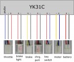
throttle is fairly obvious (5V out, 0-4V signal in)
brake light triggers if you close the brake switch
and will power 24V 5Watt braking lights (24V out)
brake means a switch that triggers as soon as you hit the brake pedal
(grab the lever) to shut down the motor (5V? closure)
chrg. port is a 24V line that will charge your batteries
if you connect a matching 24V charger. (24V in)
key switch is your on off switch (on closed; off open)
you can just hotwire the two and you end up with an always on device. (5V? closure)
motor (24V out) and
battery (24V in) again should be obvious.
the following connections MUST be made:
battery
motor
key switch (at least shortened out)
throttle
brake really SHOULD be made to not only save the batteries, but also not counteract the brake!
other connections are optional.
it's not an active brake system of any kind.
And you will not find Internal wiring diagrams for most commercial controllers,
all you need to know is what cable (connector) is doing what so that you not mess up your connections.
'sid
[EDIT]
Sorry, couldn't find a descriptive image, so I had to make one...
to my best knowledge this is the wiring of a YK31c that I believe you already ordered:
throttle is fairly obvious
(5V out, 0-4V signal in)brake light triggers if you close the brake switch
and will power 24V 5Watt braking lights (24V out)
brake means a switch that triggers as soon as you hit the brake pedal
(grab the lever) to shut down the motor (5V? closure)
chrg. port is a 24V line that will charge your batteries
if you connect a matching 24V charger. (24V in)
key switch is your on off switch (on closed; off open)
you can just hotwire the two and you end up with an always on device. (5V? closure)
motor (24V out) and
battery (24V in) again should be obvious.
the following connections MUST be made:
battery
motor
key switch (at least shortened out)
throttle
brake really SHOULD be made to not only save the batteries, but also not counteract the brake!
other connections are optional.
Sorry?so can i connect the two wires of the brake ?
connect?.. you should connect them yes, to a SWITCH
that closes as soon as you step on the brake.
or do you want to short them out (permanently close that circuit)
then NO, that will shut down the motor permanently.
Wait.. or is that an opening switch? I can't remember...
I'm sure you'll notice
Anyways,
at first do NOT connect anything to the brake connector, and try to run the motor (bench test.. no kart, no moving parts except the motor shaft)
short it (still pushing the throttle) it should stop the motor.
(closing switch)
if it doesn't run at first, again short it still pushing the throttle;
it should start to run (opening switch)
you can attach a small 24V 1Amp flick switch instead of shortening the brake connector to test,
but do not forget to remove said switch later, you do not want a permanent switch there
'sid
WOOD??
Well, I guess a 500W powered 10km/h kart made of wood is okay (reads.. safe enough)
But I'm not sure that it's a good idea...
What do you have in mind designwise?
'sid
Well, I guess a 500W powered 10km/h kart made of wood is okay (reads.. safe enough)
But I'm not sure that it's a good idea...
What do you have in mind designwise?
'sid
thanks
i'm thinking of making the gokart out of wood, do you have any experience with this ? would it be strong enough ?
greetz
Don't make out of wood!!!!
dcastillo
New member
termites

sorry couldnt resist
sorry couldnt resist
regen elec go-kart
Bro this dav from India !!Seems lik you hav gr8 insight into this electric go-kart .., i"m doing a project on this but other than principles i was not able to find any useful practical analysis untill i saw your blog here .., but i still need a deep understanding into this project being implemented .I'm trying to implement two DC motors on the back wheel &apply regenerative system to this go-kart &do lik small study cum working model!!
So, bro can you help me In understanding this working of electric system in this go kart to produce a acceleration of around 20km/h with the vehicle kerb weight of nearly 200kg .., I'm doing literature survey on this but experts advice always is the best..., So' really thank you for your help
Bro this dav from India !!
Seems lik you hav gr8 insight into this electric go-kart .., i"m doing a project on this but other than principles i was not able to find any useful practical analysis untill i saw your blog here .., but i still need a deep understanding into this project being implemented .I'm trying to implement two DC motors on the back wheel &apply regenerative system to this go-kart &do lik small study cum working model!!So, bro can you help me In understanding this working of electric system in this go kart to produce a acceleration of around 20km/h with the vehicle kerb weight of nearly 200kg .., I'm doing literature survey on this but experts advice always is the best..., So' really thank you for your help
- Status
- Not open for further replies.