Viper Off Road Build

Status
Not open for further replies.

gjpgonzo

New member
Messages
109
Reaction score
0
Location
Boston Area
Houston we have a problem!

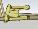
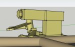
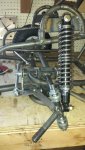
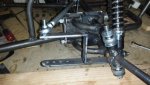
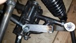
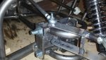
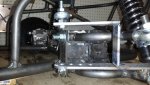
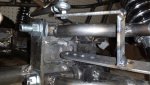
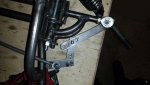
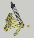
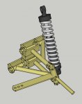
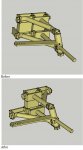
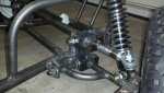
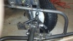
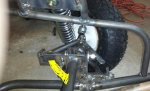
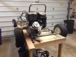
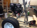
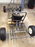
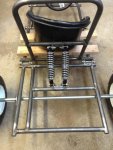
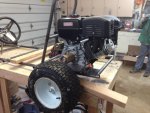
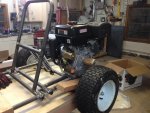
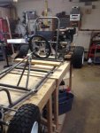
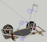
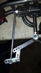
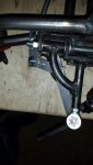
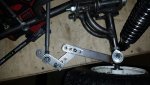
Ok, newbie mistake / problem, since I modified the design to add extra support to the A-Arms, I didn’t foresee the impact to the turning radius. I have tinkered around with a possible solution and have mocked up the following (pics). This allows the steering arms to swing at the amount they should, my questions is, am I going about it wrong? Should I do it this way? Is there any danger doing it like this?
 

Attachments

  • Full OUT.jpg
    Full OUT.jpg
    60.6 KB · Views: 26
  • Full-IN.jpg
    Full-IN.jpg
    65.8 KB · Views: 14
  • Mock Up with tire on.jpg
    Mock Up with tire on.jpg
    76.2 KB · Views: 16
  • Mock Up.jpg
    Mock Up.jpg
    66.7 KB · Views: 13

fowler

New member
Messages
5,463
Reaction score
17
Location
Bullsbrook West Aus
one would assume u would weld them solid

but u will loose your akerman

any reason u cant run the tie rod inside the a a arm mount
the steering arms look mightily long

take a shot from the side parallel to the ground
u may be able to cut out a piece of the a arm mount to allow the tie rod to fit though
 

gjpgonzo

New member
Messages
109
Reaction score
0
Location
Boston Area
one would assume u would weld them solid

but u will loose your akerman

any reason u cant run the tie rod inside the a a arm mount
the steering arms look mightily long

take a shot from the side parallel to the ground
u may be able to cut out a piece of the a arm mount to allow the tie rod to fit though

Like this, would the up and down movement concern you?
 

Attachments

  • Modify A Arm.JPG
    Modify A Arm.JPG
    44.2 KB · Views: 10
  • Modify A Arm2.JPG
    Modify A Arm2.JPG
    27.9 KB · Views: 10
  • Mock Up A Arm3.jpg
    Mock Up A Arm3.jpg
    91.5 KB · Views: 33
Last edited:

OzFab

Well-known member
Messages
15,615
Reaction score
69
Location
Warwick Qld, Australia
One thing I've learned through watching builds like this is the tie rods need to pivot at the same point as the A arms to prevent this situation &, more importantly, bump steer. Due to the nature of the design, those long tierods will never work successfully...
 

gjpgonzo

New member
Messages
109
Reaction score
0
Location
Boston Area
One thing I've learned through watching builds like this is the tie rods need to pivot at the same point as the A arms to prevent this situation &, more importantly, bump steer. Due to the nature of the design, those long tierods will never work successfully...

Then please please what should I do?
 

OzFab

Well-known member
Messages
15,615
Reaction score
69
Location
Warwick Qld, Australia
First you need to create a steering rack the same width as the front of the frame, between the A arm mounts & attach the tie rods between it & the spindles.

A simple rack can be as basic as a length of flat stock running in guide brackets or as complex as an actual saw tooth rack & pinion...
 

fowler

New member
Messages
5,463
Reaction score
17
Location
Bullsbrook West Aus
what id do is start again on the a arm mounts

run the front of the shockie hoop down to the bottom rail
this is the rear a arm mounts
then run a tube from where the rear mounts are across to the front of the frame
this is for the top front mount
mount the lower arm to the bottom of the frame

would look a bit neater
and i dont really know what to do with the setup as it is

that top support is right in the way

as for the R&P
bugger it i say
u can shorten down a car rack real easy
i used only a grinder and welder and it took 3 hrs and alot of patience

but really with that much travel u wont notice the bump steer
anyway as i found out

the rack does have zero bump steer at straight ahead
but as soon as u turn it of course gos all outta line and theres no point

my first buggy i made the rack the perfect width
with my new buggy other peoples R&D has found a longer rack(one that sticks out each side a bit)
doesnt only give u a better turning circle but when u drop the front end under brakes or u land a bit or air as the suspension moves it pulls the wheels in a bit
so in those exteme load circumstances the wheels have some toe in, this leads to fewer lower a arm failures as the wheels exert an inward force as they track together
instead of a straight ahead or outward force

just run a bell crank as what is appears was the original plan
simple cheap
shouldn't be a problem with a few inches or travel
 

gjpgonzo

New member
Messages
109
Reaction score
0
Location
Boston Area
what id do is start again on the a arm mounts

run the front of the shockie hoop down to the bottom rail
this is the rear a arm mounts
then run a tube from where the rear mounts are across to the front of the frame
this is for the top front mount
mount the lower arm to the bottom of the frame

would look a bit neater
and i dont really know what to do with the setup as it is

that top support is right in the way

as for the R&P
bugger it i say
u can shorten down a car rack real easy
i used only a grinder and welder and it took 3 hrs and alot of patience

but really with that much travel u wont notice the bump steer
anyway as i found out

the rack does have zero bump steer at straight ahead
but as soon as u turn it of course gos all outta line and theres no point

my first buggy i made the rack the perfect width
with my new buggy other peoples R&D has found a longer rack(one that sticks out each side a bit)
doesnt only give u a better turning circle but when u drop the front end under brakes or u land a bit or air as the suspension moves it pulls the wheels in a bit
so in those exteme load circumstances the wheels have some toe in, this leads to fewer lower a arm failures as the wheels exert an inward force as they track together
instead of a straight ahead or outward force

just run a bell crank as what is appears was the original plan
simple cheap
shouldn't be a problem with a few inches or travel

Can you help with showing me some pictures of examples?


WHAT if I did this???????
 

Attachments

  • Mock Up 1-5.jpg
    Mock Up 1-5.jpg
    73.7 KB · Views: 17
  • Mock Up 1-4.jpg
    Mock Up 1-4.jpg
    90.6 KB · Views: 13
  • Mock Up 1-3.jpg
    Mock Up 1-3.jpg
    84.4 KB · Views: 14
  • Mock Up 1-2.jpg
    Mock Up 1-2.jpg
    80.7 KB · Views: 15
  • Mock Up 1-1.jpg
    Mock Up 1-1.jpg
    81.3 KB · Views: 17
  • Mock Up.jpg
    Mock Up.jpg
    66.7 KB · Views: 15
  • Reverse A-1.JPG
    Reverse A-1.JPG
    46.6 KB · Views: 9
  • Reverse A.JPG
    Reverse A.JPG
    46.2 KB · Views: 11
Last edited:

gjpgonzo

New member
Messages
109
Reaction score
0
Location
Boston Area
Before and after

Please any help would be greatly appriciated!!!!!!!!!:surrender::surrender::surrender:

Would the after work in this pic?
 

Attachments

  • Before and After.JPG
    Before and After.JPG
    55.2 KB · Views: 7

exenos

Project Nut
Messages
1,217
Reaction score
0
Location
Ontario, Canada
Both of your solutions that you posted would work by neither of them are ideal. The first one with the re done spindles may be your best bet. It has potential to cause bump steer but I don't think that you are going to have enough travel to worry about it.

Sent from my XT1032 using Tapatalk
 

gjpgonzo

New member
Messages
109
Reaction score
0
Location
Boston Area
Both of your solutions that you posted would work by neither of them are ideal. The first one with the re done spindles may be your best bet. It has potential to cause bump steer but I don't think that you are going to have enough travel to worry about it.

Sent from my XT1032 using Tapatalk

OK, made the change to the A-Arms and supports last night, check them out, it's not pretty, but I think it will work well. Learning allot from the mistakes. Next time should go allot smoother.
 

Attachments

  • Re-Fig1.jpg
    Re-Fig1.jpg
    74.5 KB · Views: 19
  • Re-Fig2.jpg
    Re-Fig2.jpg
    67.8 KB · Views: 21

exenos

Project Nut
Messages
1,217
Reaction score
0
Location
Ontario, Canada
That would work very well. You may want to put a vertical support as well but I dont think you will need it because the upper arm wont be taking much if any vertical force, mainly horizontal.
 

gjpgonzo

New member
Messages
109
Reaction score
0
Location
Boston Area
Progress Pictures

Thank you all for your ongoing help!
 

Attachments

  • mid6.jpg
    mid6.jpg
    93.9 KB · Views: 20
  • mid5.jpg
    mid5.jpg
    73.4 KB · Views: 19
  • mid4.jpg
    mid4.jpg
    96.9 KB · Views: 20
  • mid3.jpg
    mid3.jpg
    97.8 KB · Views: 22
  • mid2.jpg
    mid2.jpg
    101.2 KB · Views: 24
  • mid7.jpg
    mid7.jpg
    90.8 KB · Views: 17
  • mid8.jpg
    mid8.jpg
    96.7 KB · Views: 15
  • mid9.jpg
    mid9.jpg
    100.5 KB · Views: 15

mysteryboy28

New member
Messages
1,582
Reaction score
11
Location
Lansing, MI
Shocks are too centered and far away from strong support. You need to spread them out more. Otherwise metal is gonna be bending and flexing in a bad way! The shocks should be much closer to the tires, and the tops mounted to points that have weight support (not the middle of your back!).
 

gjpgonzo

New member
Messages
109
Reaction score
0
Location
Boston Area
Shocks are too centered and far away from strong support. You need to spread them out more. Otherwise metal is gonna be bending and flexing in a bad way! The shocks should be much closer to the tires, and the tops mounted to points that have weight support (not the middle of your back!).

That's what the design calls for, i'll move them if it becomes a problem.
 

Poboy kartman

Senior Moments Member
Messages
12,461
Reaction score
69
Location
White Settlement Texas
While I don't necessarily agree with Mysteryboy on shock location. ... ( nor disagree)... it did bring to my attention that you are going to be putting some force on that seat back that has no bracing on the front end. .....
 

gjpgonzo

New member
Messages
109
Reaction score
0
Location
Boston Area
While I don't necessarily agree with Mysteryboy on shock location. ... ( nor disagree)... it did bring to my attention that you are going to be putting some force on that seat back that has no bracing on the front end. .....

it will be supported by the nerf bar.
 

Attachments

  • Connecting Nerf and Roll cage.JPG
    Connecting Nerf and Roll cage.JPG
    82 KB · Views: 6
Status
Not open for further replies.
Top