andrewmacc
Canadian Wonderboy
Looks a little cold, need to turn up the heat and down the feed.
Is that 120v or 220v?
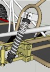
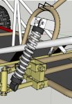
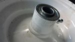
You can tell it's 120v because of the severe cold lap on almost all the joints. I was gonna keep my big yap shut because I know that not everybody appreciates that kind of criticism, but the welds holding the tube onto the bracketside of the A-arm are very concerning.
The welds holding the bolt onto the spindle are even moreso. I am intensely skeptical of 120v welders for this very reason.. after a lot of hours under the hood burning 1/16" wire at over 300 amps, 120v welders require certain prep-work to even remotely guarantee proper penetration into the joint. Fusion is not necessarily penetration, and well, vice versa.
A hot root bead followed by appropriately placed cap passes would have been much more preferable than a wide (and thereby ineffective) weave bead, when you are using equipment that is inadequately rated for the weldment material.
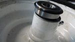
As well, the reinforcement tube of the A-arm should have been placed further up on the tube to prevent bending. IMO, the HAZ of the weld is going to make the tube more susceptible to bending after the weld joint now, nearer to the spindle, where it will see the largest moment of bend stress.
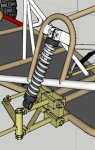
Also, in terms of suspension design, parallel A-arms are not the most effective. The upper arm should decline downward at an angle greater than the lower A-arm. But that's a whole 'nother ballgame of discussion!
Sorry dude, not bashing, you're building a wicked project and can't wait to see how it turns out, just don't want it falling apart on you when you need the strength the most!