Torque converter sprocket location?

greenkidd

New member
Messages
23
Reaction score
9
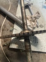
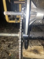
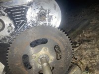
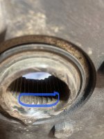
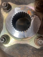
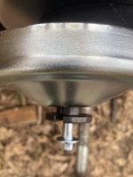
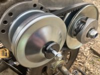
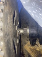
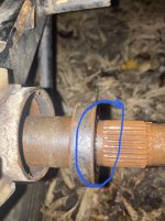
I was able to get back out to look over things. It appears that the drive sprocket should be on the splines on the shaft? I'm assuming that anyway because the brake rotor goes on the splines on the other side. With that said, IF I can grind off the welds on the sprocket assembly, it should slide onto the splines on that side of the shaft, correct? Another thing, the bearing on the passenger side seems to be stuck; I can get it to wobble a tiny bit but it doesn't want to slide off. Could there be a lip there keeping it from coming off (area circled in blue)? If so, will it hurt to try prying or pounding it off?
 

Attachments

  • IMG_4002.jpg
    IMG_4002.jpg
    3.1 MB · Views: 4
  • IMG_4004.jpg
    IMG_4004.jpg
    573 KB · Views: 4

JimD

Well-known member
Messages
318
Reaction score
682
Location
Naperville, IL
Wire brush the splines real good and if you can take the sprocket off that you think has the splines in it just to verify. If they are in there then clean those out on your drill with a wire brush also. The keyway in the sprocket carrier if it has splines really confuses me. But you never know why someone else did something unless they don't own a BFH. Just take your grinder and cut off the bearing shell it worthless.
 

greenkidd

New member
Messages
23
Reaction score
9
Wire brush the splines real good and if you can take the sprocket off that you think has the splines in it just to verify. If they are in there then clean those out on your drill with a wire brush also. The keyway in the sprocket carrier if it has splines really confuses me. But you never know why someone else did something unless they don't own a BFH. Just take your grinder and cut off the bearing shell it worthless.
Yeah, I'm trying to figure this thing out, including where and why they welded the drive sprocket on the shaft. At this point, I don't think the sprocket carrier has a keyway; it appears to only have splines (I haven't seen a keyway or key on the shaft or sprocket). I like the idea of the grinder for the old bearing!
 

greenkidd

New member
Messages
23
Reaction score
9
Thanks for the help and information everyone! I finally removed the axle and ground off the welds from the drive sprocket. It slides freely onto the axle splines and I just need new bearings. However, after reading the posts linked below, I’m wondering if there’s a reason why the previous owner welded the sprocket onto the axle. After researching, my kart is a Tomberlin Firefox 620 just like the poster in the link.


greenkidd

New member
Messages
23
Reaction score
9
Yeah, good call on those ideas Red and Denny. Based on his photos, if mine ends up having the same spacing (I ASSume it will since it has the Mitsubishi engine), I'm thinking of two things. The first is using some steel plate or square tubing to space the engine over to the left and up. I thought I could also put a lock collar or washers on the jackshaft to space out the sprocket to the left (might still need to raise the engine too). Do either of those sound reasonable?
 

Attachments

  • IMG_4020.jpg
    IMG_4020.jpg
    1.6 MB · Views: 3

JimD

Well-known member
Messages
318
Reaction score
682
Location
Naperville, IL
I would do the tubing to slide over the axle.. It means taking it all apart after you put it together the first time to cut the tubing to the exact length you measure when you get all the pieces in line. The tubing you use is electrical conduit. Yes, it is a lot of work but worth it. The problem with the collars if you decide to go that route is the shaft may be metric and the collars are for English sizes just measure to make sure before you order or you will have a bunch of parts you cannot use. You have gone through a lot of work and it is worth going the extra mile to make it so it last a LONG time. Don't use washers because they will free spin on the axle and groove it to the point where they will actually cut through it. I have seen it happen on crankshafts both 2 cycle and 4 cycle. I always use fiber washers on the cranks for this very reason.
 

madprofessor

"Loose Cannon Creations"
Messages
2,899
Reaction score
956
Location
Jacksonville, Florida
About those lock collars................ The solid ones with a setscrew or two should all be melted down for scrap. The "split" collars that are split in only one place are decent, but still require you to R&R everything on the axle to put them on or to R&R them later.
I won't use anything but "DOUBLE-SPLIT" collars because you can put them on/off anywhere in a minute flat without any R&R of anything else on the axle. I think I've got about 20 of them on current kart.
1" Bore Double Split Shaft Collar Black Oxide Set Screw Style (4 PCS) (jeremywellindustry.com)
3/4" Bore Double Split Shaft Collar Black Oxide Set Screw Style (4 PCS (jeremywellindustry.com)
 

greenkidd

New member
Messages
23
Reaction score
9
I reinstalled the axle along with the old torque converter mounting plate to get an idea of how much room I'll need (the jackshaft is bent!). As seen from the photos, the engine needs to slide to the left a bit and probably to the back. The bolt holes on the frame are slotted so I can move the engine back and forth but not side to side. I went ahead and ordered an adjustable mounting plate from OMB so I can move the engine towards the axle sprocket.
 

Attachments

  • IMG_4058.jpg
    IMG_4058.jpg
    2.5 MB · Views: 3
  • IMG_4050.jpg
    IMG_4050.jpg
    2.7 MB · Views: 3

JimD

Well-known member
Messages
318
Reaction score
682
Location
Naperville, IL
How do you know the jackshaft is bent? Not saying it cannot be but they are pretty difficult to bend since the stress on the sprocket is so close to the t/c plate. I would shim out the sprocket on the jackshaft and them put the driven on to make sure you still have enough shaft to get the nut on that is going to hold it in place. It all fit together at one time, so think positive . Can you gain anything by reversing the axle sprocket and turning it around 180 degrees. I really cannot tell from the picture.
 

greenkidd

New member
Messages
23
Reaction score
9
The jackshaft or the plate itself is bent based on how it was set up before with the sprocket on the end of the shaft. The shaft itself won't slide out of the TC plate and I have a hard time putting the old drive sprocket back on it. Good point on trying to shim out the sprocket on the jackshaft; it doesn't need a ton of space. The axle sprocket is already the closest it can get and is actually up against the bearing already so it can't go inboard any further.
 

greenkidd

New member
Messages
23
Reaction score
9
Here I am asking questions again. Using that OMB adapter plate, I'm able to line up the sprockets. However, what I'm noticing is when I place the drive sprocket on the axle splines, there is a bit of wobble. It does appear that some of the splines on the sprocket (and axle) are a bit worn. I don't want this causing issues with it wobbling and kicking the chain off or damaging anything. New axles or sprockets are not available. Is there anything I can do to the sprocket splines or axle splines to tighten it up and make it a better/tighter fit? I've considered some form of Loctite. In the photos, the biggest wear areas I circled in blue. The other photo shows what I had to grind off the outboard side with the previous welding.
 

Attachments

  • IMG_4088.jpg
    IMG_4088.jpg
    262.7 KB · Views: 2
  • IMG_4091.jpg
    IMG_4091.jpg
    1.2 MB · Views: 2

JimD

Well-known member
Messages
318
Reaction score
682
Location
Naperville, IL
Get some Loctite 620 and apply some to the splines on both the axle and sprocket splines. First clean them out real good with a wire brush and some acetone. The 620 will expand .020 which will help out some but if you have more slop then that then I would weld a 1" extension onto that spline and put two 5/16" square head bolts and put two flats on the axle where the bolts hit and torque them down real tight. This will hold it for awhile. When you do the welding put a shaft through the two pieces to keep them perfectly aligned. This will cut down on the length of the spacers you will be needing. Use 1 3/4" diameter or 2". I got a ton of it laying around my shop and will make you up the spacer but I am a crapy welder. This is why most axles have 1/4" keyways. You can replace the keys but once the splines go you are screwed.
 

greenkidd

New member
Messages
23
Reaction score
9
Well, I'm back again with more stupid questions. The bolt holder on the driver pulley butts up against the engine shaft (photo below). Am I missing something here? I used the spacer included with the kit but guessing I did something wrong. Instead of the bolt holder piece, I have a washer that seems to work with a shorter bolt.
 

Attachments

  • IMG_4149.jpg
    IMG_4149.jpg
    580.5 KB · Views: 1
  • IMG_4147.jpg
    IMG_4147.jpg
    1.3 MB · Views: 1
Top