Start/kill switches and Starter hookup

Status
Not open for further replies.

HONEYBADGERFTW

New member
Messages
116
Reaction score
4
Location
Houston, TX
Briggs V twin Vanguard. I’m not sure if I can, but I would like to have a push button start switch (2 wire if possible since I have a switch that is that), and a separate kill switch (two terminal latching push button). Problem is I have no clue how to accomplish that. So if someone who is knowledgeable that can help. And everything is just set in place for the picture, I still have modifications to do for engine installation etc.

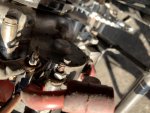
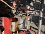
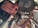
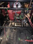
1- Negative battery cable
2- Positive battery cable
3- Two thin wires coming from underneath the shroud
4- Wire coming from an electrical block that has two yellow wires going underneath the shroud
5- From starter solenoid where the + battery cable is connected as well
6- Wire from battery + cable (went to the old “key switch” I believe )
The green ⭕️ Is where a ground goes from the starter to body/engine mount/grounding point I think?
 

Attachments

  • 60A85BF4-5312-4BA3-AA19-B5AD5D5C63C4.jpg
    60A85BF4-5312-4BA3-AA19-B5AD5D5C63C4.jpg
    361.4 KB · Views: 28

mckutzy

Well-known member
Messages
8,353
Reaction score
108
Location
bc, canada
Im sorry you not getting any replies... these big V-twin Honda/Predator and Briggs engines are not quite that prevalent here on this forum... Only a few have them...
 

HONEYBADGERFTW

New member
Messages
116
Reaction score
4
Location
Houston, TX
Yeah I’m just frustrated because it seems like it’s something simple but I can’t figure it out lol. I got this engine from a trade and know nothing about how it is supposed to be hooked up because there were some “it’ll work “ type fixes on it. The schematics I can find are generic or really confusing to me. This project has turned into one obstacle after another, so surely when I finally get it done it’ll be awesome ��
 

landuse

Moderator
Staff member
Messages
18,755
Reaction score
533
Location
Pietermaritzburg, South Africa
Yeah I’m just frustrated because it seems like it’s something simple but I can’t figure it out lol. I got this engine from a trade and know nothing about how it is supposed to be hooked up because there were some “it’ll work “ type fixes on it. The schematics I can find are generic or really confusing to me. This project has turned into one obstacle after another, so surely when I finally get it done it’ll be awesome ��

Maybe send Anderkart a PM. He doesn't check the forum regularly, so a PM regarding the engine numbers he asked for might help you out more
 

anderkart

Moderator
Messages
6,427
Reaction score
374
Location
Surprise Arizona USA
"3- Two thin wires coming from underneath the shroud"

The wiring diagrams indicate that one (or possibly both) of these 2 black wires connect to your magneto and are used for the kill switch. If that's correct, you should get spark to start the engine with both of these wires completely disconnected; then you should discover that grounding one (or both) of these wires will kill spark to shut the engine off. If your testing confirms this, you could connect one (or both) of these black wires to either terminal of your two terminal latching push button switch; and then you'd just need to wire the other terminal of this switch to ground.

_______________

"The green ⭕️ Is where a ground goes from the starter to body/engine mount/grounding point I think"?

Nope that's not a ground, that terminal activates your starter solenoid. Your push button start switch should work fine, it just needs to send power to this terminal to activate the solenoid; then your solenoid should send power along to the starter through the battery cables.
 

HONEYBADGERFTW

New member
Messages
116
Reaction score
4
Location
Houston, TX
Awesome!
So + battery to one side push switch and the other side of push switch to the terminal that activates solenoid. Solenoid has a +battery connection to one side, other side goes to starter. Both the solenoid and starter are grounded via bonding/connected to the engine. Correct?

What is wire #4? And where does it go?
 

Attachments

  • 181F1C05-2966-4F62-AC6A-877F382AE28C.jpg
    181F1C05-2966-4F62-AC6A-877F382AE28C.jpg
    241.2 KB · Views: 8
  • 5999CEFD-5DEB-4A71-B64E-1BD6E3AB02CF.jpg
    5999CEFD-5DEB-4A71-B64E-1BD6E3AB02CF.jpg
    343.3 KB · Views: 7
  • 2BD43D32-C3CB-4C42-B7FE-B832C06CF9F8.jpg
    2BD43D32-C3CB-4C42-B7FE-B832C06CF9F8.jpg
    345.9 KB · Views: 6

anderkart

Moderator
Messages
6,427
Reaction score
374
Location
Surprise Arizona USA
Awesome!
So + battery to one side push switch and the other side of push switch to the terminal that activates solenoid. Solenoid has a +battery connection to one side, other side goes to starter. Both the solenoid and starter are grounded via bonding/connected to the engine. Correct?

What is wire #4? And where does it go?

Yes, yes & yes.

I agree with cleatusj, your wire #4 is the output from your charging coil and voltage regulator. It needs to be connected to + battery.
 

anderkart

Moderator
Messages
6,427
Reaction score
374
Location
Surprise Arizona USA
Your welcome.

Something else you should do is install two 15-amp inline fuses to protect things in case of a short.

I'd install both fuses at the starter solenoid post along with the positive cable that goes to your battery. Then connect one of the inline fuses to your #4 wire, and connect the other fuse to the wire that's supplying power to your push button start switch.

I'd use 12 or 14 gauge wire to hook up your push button start switch.

ATO fuse holders are available at most any auto parts store:
 
Status
Not open for further replies.
Top