ShredderII build who wants to see it ?

lug-nuts

Active member
Messages
84
Reaction score
117
Location
Riverton UT
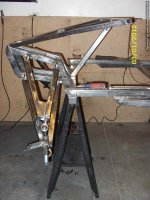
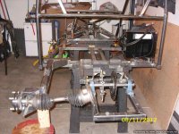
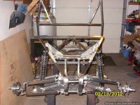
So the shredderII was designed by a company called ubuilditplans they went out of business and the plans are almost impossible to get anymore. I was luck enough to have purchased the plans 11 years ago and built the thing, with some modifications of course.

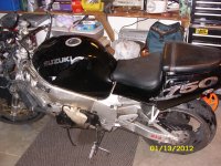
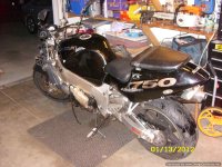
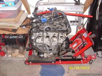
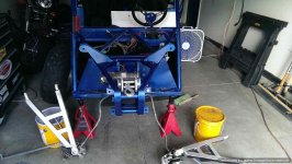
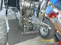
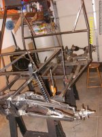
The original build called for a industrial up to 50hp motor, well I took it a bit further and installed a 135hp GSXR 750 motor. Streched it a little and shortened the cage height. changed up a few other things along the way and learned a lot !

I was a member of minibuggy.net which is no longer around, I noticed there werent very many people building these anymore. I think because the market has so many other options and its a ridiculous amount of time, money and effort.

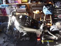
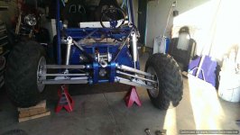
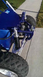
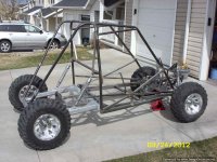
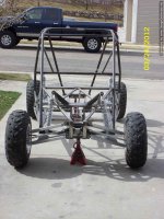
I have around 650 to 700 hours in my build start to finish, and its a solid buggy. I beat it like it owes me money ever time I take it out. It just keeps chugging along. There were a few mishaps and broken parts the first couple times I took it out, but that was my fault. Like one of my CV's failed, I had too much max angle and the axle came out. Stuff like that.

20180802_153715.jpg
 

lug-nuts

Active member
Messages
84
Reaction score
117
Location
Riverton UT
This is a budget build so I tried to do it as inexpensively as possible. Also These are what I paid 10 plus years ago, so take that for what its worth.

The first thing I did was buy a powerplant (donor bike) 1999 Suzuki GSXR 750. The plans called for a much smaller motor. Got the bike for 600 bucks
 

Attachments

  • SN850606.JPG
    SN850606.JPG
    3.1 MB · Views: 7
  • SN850607-Optimized.JPG
    SN850607-Optimized.JPG
    92.8 KB · Views: 6

lug-nuts

Active member
Messages
84
Reaction score
117
Location
Riverton UT
Tore down the bike and sold off all the parts I didnt want, I made my 600 back plus an addtional 2 grand on the parts (who knew?)
 

Attachments

  • SN850614.JPG
    SN850614.JPG
    86.6 KB · Views: 7
  • SN850617.JPG
    SN850617.JPG
    95.6 KB · Views: 7

lug-nuts

Active member
Messages
84
Reaction score
117
Location
Riverton UT
Getting the all the steel and tabs cut, took me about 2 weeks. Then I started tacking everything together. Side note, the plans call for 10 different sizes of flat stock. I would buy 3" X 1/8" flat stock and cut it down to the tabs you need. That will save a ton of time and not to mention all of the flat stock you have left over. Just my 2 cents, anyone building this can do it however they like.
 

Attachments

  • SN850642-Optimized-1.JPG
    SN850642-Optimized-1.JPG
    70.4 KB · Views: 2
  • SN850644-Optimized.JPG
    SN850644-Optimized.JPG
    83.8 KB · Views: 2
  • SN850645-Optimized.JPG
    SN850645-Optimized.JPG
    41.4 KB · Views: 2
  • SN850647-Optimized.JPG
    SN850647-Optimized.JPG
    46.2 KB · Views: 2
  • SN850648-Optimized.JPG
    SN850648-Optimized.JPG
    97.6 KB · Views: 2
  • IMAG0057.jpg
    IMAG0057.jpg
    34.9 KB · Views: 2
  • IMAG0058.jpg
    IMAG0058.jpg
    92.5 KB · Views: 2

lug-nuts

Active member
Messages
84
Reaction score
117
Location
Riverton UT
Here's a little tip, I had an old 12" miter saw kicking around so I removed the guards and purchased a 12" metal cutting blade. Its way better than a chop saw and all the angles are easy to find with the built in gauge.
 

lug-nuts

Active member
Messages
84
Reaction score
117
Location
Riverton UT
Here's the front end where the A-arms attatch
 

Attachments

  • SN850656-Optimized.JPG
    SN850656-Optimized.JPG
    78.5 KB · Views: 2
  • SN850661-Optimized.JPG
    SN850661-Optimized.JPG
    47.9 KB · Views: 2
  • SN850662-Optimized.JPG
    SN850662-Optimized.JPG
    102.2 KB · Views: 2

lug-nuts

Active member
Messages
84
Reaction score
117
Location
Riverton UT
I made my own front hubs and attached 4 wheeler brake rotors to them. I should have jus bought front hubs/rotors and spindles from a sideXside that someone was parting out (time & money saver)
 

Attachments

  • SN850664-Optimized.JPG
    SN850664-Optimized.JPG
    52.1 KB · Views: 6
  • SN850666-Optimized.JPG
    SN850666-Optimized.JPG
    47.7 KB · Views: 6
  • SN850674-Optimized.JPG
    SN850674-Optimized.JPG
    92.9 KB · Views: 6
  • SN850673-Optimized.JPG
    SN850673-Optimized.JPG
    99.5 KB · Views: 6

lug-nuts

Active member
Messages
84
Reaction score
117
Location
Riverton UT
It's a lot of work, and its easy to start treating it like a job during the whole build process. Its unique, and if it breaks I know exactly how to fix it.
 

lug-nuts

Active member
Messages
84
Reaction score
117
Location
Riverton UT
The front end assembled and put together, one thing I would do different is the upper A arm it needs to be as wide as you can get so it wont interfere with a coil over shock. I had to modify this after the fact. see pics
 

Attachments

  • SN850681-Optimized.JPG
    SN850681-Optimized.JPG
    78.2 KB · Views: 3
  • SN850684-Optimized.JPG
    SN850684-Optimized.JPG
    83.6 KB · Views: 3
  • IMAG0001.jpg
    IMAG0001.jpg
    82.7 KB · Views: 3
  • IMAG0064.jpg
    IMAG0064.jpg
    64.7 KB · Views: 4
  • IMAG0041.jpg
    IMAG0041.jpg
    69.7 KB · Views: 4
  • IMAG0081_zps172ee166.jpg
    IMAG0081_zps172ee166.jpg
    41.1 KB · Views: 4

lug-nuts

Active member
Messages
84
Reaction score
117
Location
Riverton UT
Heres a few pics of the brake pedal installed. I modified the steering set up in this build. The plans call for chains, bearings, and all sorts of witchcraft to align everything with the steering gear/steering wheel. I used a steering shaft with u joints.
 

Attachments

  • SN851053.JPG
    SN851053.JPG
    46 KB · Views: 5
  • SN851056.JPG
    SN851056.JPG
    46.9 KB · Views: 5
  • SN851059.JPG
    SN851059.JPG
    45.6 KB · Views: 5

lug-nuts

Active member
Messages
84
Reaction score
117
Location
Riverton UT
You may notice there is not a clutch pedal, that is because I sent my clutch out to company called autoclutch. My clutch is centrifugally actuated by engine speed. So u just jam it in gear and hit the gas to shift just let off the gas for a moment and shift. No touchy pedal or hand clutch to deal with.
 

Attachments

  • 043.jpg
    043.jpg
    52.6 KB · Views: 4
  • 040.jpg
    040.jpg
    46.4 KB · Views: 4
  • 041.jpg
    041.jpg
    49 KB · Views: 4

lug-nuts

Active member
Messages
84
Reaction score
117
Location
Riverton UT
I can adjust when the clutch engages by how many of those ball bearing i put in it. The more I put in, the higher the RPM when it engages. Im currently engaging around 1500 rpm.
 

lug-nuts

Active member
Messages
84
Reaction score
117
Location
Riverton UT
The rear trailing arms were a bit short in my opinion. Plus with the powerplant I am putting in this I needed a little more length. So I made it a foot longer. I also ditched the plans jackshaft setup for a easier install. I used cv axles and hubs for a 1985 chevy S10 4X4 front axles. Had a 1/4" plate cut for the diameter of the hub and drilled the mount holes into it. Just dropped it in and bolted it on.
 

Attachments

  • SN850689-Optimized.JPG
    SN850689-Optimized.JPG
    52.9 KB · Views: 3
  • SN850690-Optimized.JPG
    SN850690-Optimized.JPG
    66.8 KB · Views: 3
  • SN850691-Optimized.JPG
    SN850691-Optimized.JPG
    53.6 KB · Views: 3
  • SN850692-Optimized.JPG
    SN850692-Optimized.JPG
    58.1 KB · Views: 3
  • SN850693-Optimized.JPG
    SN850693-Optimized.JPG
    62.5 KB · Views: 3

lug-nuts

Active member
Messages
84
Reaction score
117
Location
Riverton UT
One thing I changed was the orientation of the trailing arms. The plans call for them flipped over so they are closer to the engine and drive chains. For my axles to work I flipped them over, and just out of shear dumb luck they were the correct width. I have also since cut off the shock mounts and re attached as close as I could get to the rear hub assembly.

I have had some tell me to add trussing and boxing to the trailing arms, but done the way plans say has been fine. If you look youll see a angle iron welded to the under side of the arms. The only problem I have run into is the 3/4" heim joints that attach to the rear frame have started to bend a little ( the inner heim) it makes the trailing are look out of level. Easy fix, just loosen the offending heim and turn it 180* it changes the orientation a little on the arm, but its not noticeable.
 

BrownStainRacing

Well-known member
Messages
1,367
Reaction score
1,483
You may notice there is not a clutch pedal, that is because I sent my clutch out to company called autoclutch. My clutch is centrifugally actuated by engine speed. So u just jam it in gear and hit the gas to shift just let off the gas for a moment and shift. No touchy pedal or hand clutch to deal with.
Semi automatic clutch, thats awesome!!!!!!
 

lug-nuts

Active member
Messages
84
Reaction score
117
Location
Riverton UT
There are few draw backs, but all in all I really like it. If your battery dies, theres no push starting it. So , ya....
 

lug-nuts

Active member
Messages
84
Reaction score
117
Location
Riverton UT
Next I had to tackle the "live axle" I should have looked more into a "no machine/lathe spool" setup with a miata rear end. plenty of videos on utube on that subject. When I have to replace my sprocket I have to cut off the axle flange so the sprocket will come off.

I picked up a keyed axle at the local merchandise salvage store. 1 3/16" 4 feet long for 3 bucks (SCORE) they sell all metal by weight. I had no idea the axle would be there or the size, but it was the right price. I figured I could make it work somehow.

Bought 2- 1 3/16" pillow block bearings and had 1/4" plate cut round and a hole put in the middle of them for the axle. Now I have flanges to bolt things to on the axle.
 

Attachments

  • SN850803-Optimized.JPG
    SN850803-Optimized.JPG
    60.9 KB · Views: 5
  • SN850697-Optimized.JPG
    SN850697-Optimized.JPG
    86.8 KB · Views: 5
  • SN850823-Optimized.JPG
    SN850823-Optimized.JPG
    99.8 KB · Views: 5

lug-nuts

Active member
Messages
84
Reaction score
117
Location
Riverton UT
Front end pics with temp shocks in place, I wanted these shocks to work so bad. The springs werent heavy enough to hold it up. For the budget build I ended up using monroe air shocks, but later spent some money on the ones in the earlier pics of my A arm cut/and re fit.

something I learned that you might think is self explanatory, the closer to the wheel you get the shocks, the less "weight/levereage" they have exerted on them. That means you can get away with a lighter spring. When I extended the rear trailing arms I didnt know that and I did account for it. That's the reason Im not using the original location, and have cut off the mounts there.
 

Attachments

  • SN850699-Optimized.JPG
    SN850699-Optimized.JPG
    82.6 KB · Views: 1
  • SN850694-Optimized.JPG
    SN850694-Optimized.JPG
    84.5 KB · Views: 1
Top