Razor Scooter Gas Conversion

Status
Not open for further replies.

rmm727

New member
Messages
621
Reaction score
0
Location
Brookville, PA
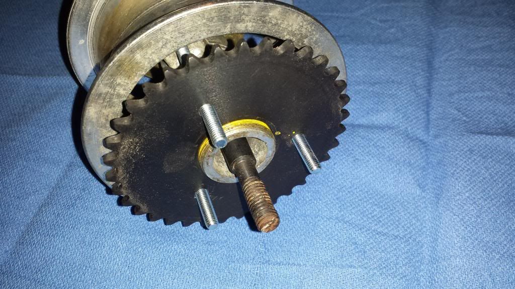
I had this Razor E300S scooter given to me some time ago. The batteries were bad and it didn't come with a charger so I decided to put a smaller gas engine on it. I had a 2 stroke Tecumseh snow blower engine that I wanted to use but its mounting method and stepped crankshaft posed some difficulties in coming up with an engine mount that wouldn’t drastically alter the scooter frame. Fast forward a bit and I now have a g100 clone from a Baja DB30 mini bike. It is slightly smaller than the Tec 2 stroke, installs in a more conventional way, and had the clutch already mounted. Now that I had the engine mounting somewhat figured out, I decided to move on to the next problem... the rear wheel sprocket. These Razor scooters use a #25 chain sprocket mounted to a freewheel.

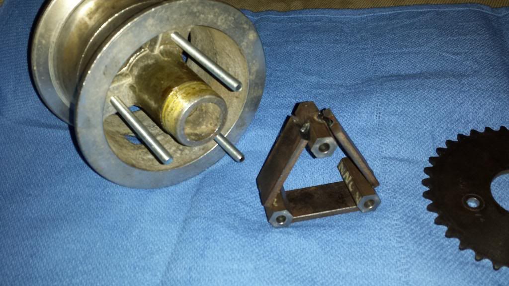
I decided to remove the freewheel and replace it with a #35 A type sprocket or a plate sprocket to some folks. The sprocket has 35 teeth and a ½” bore. I had a machinist friend bore the center to provide a slip fit over the freewheel threads. I also had him drill the (3) 6mm holes on a 60mm bolt circle.


Now that was out of the way, I measured and cut some hex stock to act as spacers. Fearing that the small 6mm bolts wouldn’t be able to handle the stress of having a sprocket attached to them, I cut 3 pcs of 3/16” x 1” band iron to tie the hex spacers together. I felt this would keep the bolts from shearing or bending.


Some more pics for now.


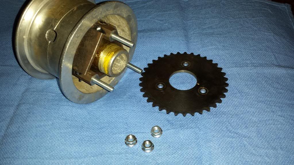
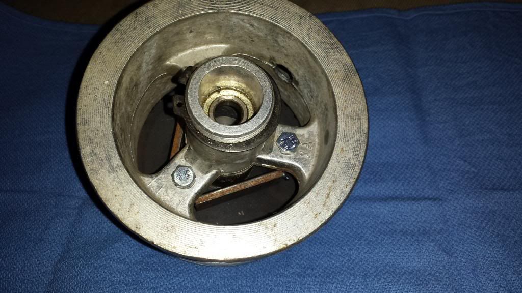
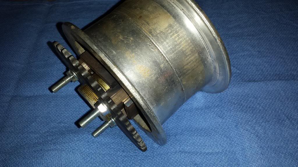
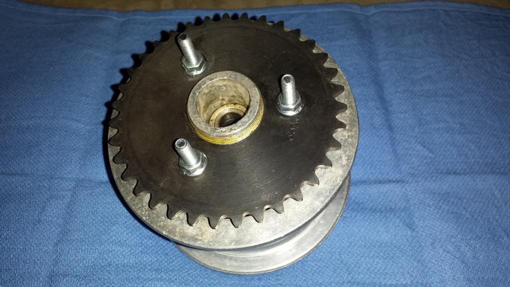
Need to finish welding the spacer, sandblast, and paint it. Also need to see if my hardware store has socket head caps screws in a length that will work for this. Then on to the engine mount.
 

rmm727

New member
Messages
621
Reaction score
0
Location
Brookville, PA
That is a concern. I am trying to do all this without modifying the original parts. I may have to buy socket head cap screws and thread them the rest of the way. I did a search on the internet one night for hardened metric all thread but don't remember if I came up with anything.
 

rmm727

New member
Messages
621
Reaction score
0
Location
Brookville, PA
Got it welded today. Asked my "helper" to wire wheel the welds with a grinder. He misheard me and ground them first. Had to spend some extra time touching them up on the belt sander. I'm not entirely happy with it but I'm not about to make 3 more spacers the exact same length. So I sandblasted it and got it in primer. I thought 8.8 was the same as grade 5. Was hoping for something in the 10.9 range but I might have to stick with what I have.
 

KartFab

Active member
Messages
3,381
Reaction score
9
Location
Dallas, TX
That's pretty neat. Have you figured out how fast it's going to go? 35 teeth doesn't seem like much, but it does have small tires.
 

rmm727

New member
Messages
621
Reaction score
0
Location
Brookville, PA
I'm going to use a bolt on jackshaft off of a Baja Warrior on the G100 clone. You can take the 16mm shaft out of it and replace that with a 5/8" shaft and 35mm OD / 5/8" ID snap ring bearings. I'm going to gear it for somewhere between 15-25 mph. I might even use my Downs Bros manual clutch on this. I picked up a 16mm ID / 3/4" pulley bore reducer for the G100's crank so it could work with that clutch. That would give me coast start ability.
 

rmm727

New member
Messages
621
Reaction score
0
Location
Brookville, PA
Here is the spacer sandblasted and primed.


I had originally planned on just sandblasting the welds but since my "helper" ground on them and since I am picky, I spent some time on the belt sander trying to clean them up. Didn't want to have to do that but sometimes it happens.
 

rmm727

New member
Messages
621
Reaction score
0
Location
Brookville, PA
Here is the bottom portion of the engine mount. This will bolt in between the frame rails and utilize 8 threaded holes that are apart of the frame. The 4 larger holes in the center were originally for the electric motor. The top outer holes are for the floorboard and also the seat when it is mounted. I made this out of a piece of what they call shielding steel. It is used to line the walls of MRI trailers. It isn't as strong as A36 plate but I don't think its that much weaker. It also seems to come in weird thicknesses that aren't typically sold. This piece is under 3/16". 1/8" was too think to do the countersunk holes.


rmm727

New member
Messages
621
Reaction score
0
Location
Brookville, PA
Today consisted of the following...I scrubbed the tire with Bleche Wite and then shined it up with Armor All. I also took some Mother's aluminum polish to the rim to clean it up a little. Should have sand blasted and painted it too but I need to make some progress on this project. I then loosely assembled the rim and figured out what length I needed to cut the bolts to. To my surprise, I was able to clamp the rim in my bandsaw and cut all the bolts at the some time.


After putting the rim together I realized I should have made the sprocket spacer wider than what I did. Looks like the chain is going to rub the tire sidewall. I'll have to buy 3 more bolts and put a washer or 2 behind the sprocket. Or I can make another spacer. I will have to think about that.


rmm727

New member
Messages
621
Reaction score
0
Location
Brookville, PA
On Friday I plasma cut the top portion of my engine mount and cut a piece of 1-1/2" square tubing to act as a riser. I didn't have time to sandblast all of it so I will have to do that later when everything is welded up.


I then laid out a few lines with a combination square and a scribe and tack welded the mount together.


It doesn't look like it in this pic but the two plates are parallel.


Here is a top view shot.


rmm727

New member
Messages
621
Reaction score
0
Location
Brookville, PA
I loosely bolted my engine mount down. With the way this mount is designed, I can't slide the wheel all the way forward. Not sure If it could to begin with but it is a concern. One thought is to change the angle cuts on the square tubing to something a little steeper. Other than that, this looks like a go. I bolted up the engine and all looks well. I need to get a pic of it all together tomorrow.
 

rmm727

New member
Messages
621
Reaction score
0
Location
Brookville, PA
Here is a pic of the scooter from the side with the engine in place.


From the front. Looks balanced and not too top heavy.


And a close up.


Got to get rid of that pvc valve.
 
Messages
242
Reaction score
0
Location
Canada, AB, Spruce Grove
I definitely agree with landuse though. That mount looks far too weak for it's motor. Is there a reason it needs to be elevated like that? Probably because of the wheel huh... Hopefully it works out alright. Maybe do some reinforcement pillars or brackets?
 

rmm727

New member
Messages
621
Reaction score
0
Location
Brookville, PA
I still think that engine is going to vibrate too much for that mount and snap it right off

Still? :lolgoku: Its the first time you mentioned it. I have been thinking about that though.

I definitely agree with landuse though. That mount looks far too weak for it's motor. Is there a reason it needs to be elevated like that? Probably because of the wheel huh... Hopefully it works out alright. Maybe do some reinforcement pillars or brackets?

By mount you mean the 2 blue strips running left to right between the frame tubes?

The engine needs elevated to clear the rear tire and to be rearward enough to allow the seat to bolt on if I choose to have it installed. If the concept works, I can cut a wider base for the engine mount and weld it directly to the frame tubes.

If anyone would like to post up a sketch of how they would go about this I would gladly consider it.
 
Status
Not open for further replies.
Top