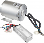
Razor Dune Buggy - Upgraded Components and then fried stuff. Advice needed..

EpsilonZero

...still cheaper than a boat!
Messages
399
Reaction score
203
I drove the dune buggy off-road with the stock axle and never bent it. That wouldn't cause the chain to ride up anyway; it would still tighten and loosen though.
 

ts2340

Member
Messages
48
Reaction score
3
yes I think it’s the last thing you said.
 

ts2340

Member
Messages
48
Reaction score
3
It’s 100% the rotor. Took off the brake and I can clearly see it’s bent. Now to find one…
 

EpsilonZero

...still cheaper than a boat!
Messages
399
Reaction score
203
Do you know where I can get one? I’ve googled and come up empty so far. Guess we can go no brakes. Lol kidding
I'd try to bend it back as true as you can. I have never seen an OEM rotor for sale.
 

ts2340

Member
Messages
48
Reaction score
3
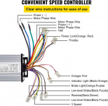
OK I'll try that tonight, hopefully. Question regarding hooking it up.. The motor/controller has different connectors then the stock motor/controller..

What are the phase and do they need connected? I'm assuming I'm going to have some leftover connectors as I don't have reverse.. Not sure what power lock is.. Actually not sure what most of those are on the controller..

1657914670932.png

1657914684565.png
 

ts2340

Member
Messages
48
Reaction score
3
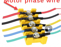
Side note, do you guys know what this yellow piece is called? Looks like it makes install much cleaner..

1657915563595.png
 

Functional Artist

Well-known member
Messages
5,654
Reaction score
3,293
Location
Toledo, Ohio
Yellow thing = terminal block or junction block

Phase wires are the main "power" wires (the controller sends current thru these wires to power the motor)
...the hall wires are the "signal" wires (sends rotor position info to the controller)

Power Lock is where your on/off switch connects

As far as throttle, just make sure the wire colors are aligned properly
Red to red(5V+)
Black to black (gnd -)
...& 3rd wire (color varies) is the 0-5V throttle position "signal' being sent back to the controller

* FYI: In the diagram above the upper wires/connectors are all "necessary"
...& the lower wires/connectors are for accessories (not necessary for the motor to function)
 

EpsilonZero

...still cheaper than a boat!
Messages
399
Reaction score
203
😩
No... it is not supposed to do that. I would check my dune buggy but I replaced the axle and I heavily modified the original. Make sure you didn't lose the little metal bushings that go in the wheels; that might be causing the problem.
 

Functional Artist

Well-known member
Messages
5,654
Reaction score
3,293
Location
Toledo, Ohio
I still think the axle (itself) may be bent. (Have you looked at it, while spinning it?)

A bent axle could make both the sprocket
...& the rotor "wobble"

If the sprocket "wobbes", it could cause your chain "riding up" issue
...& if the rotor "wobbles", it could cause your brake "binding" issue

Just sayin' ;)
 

ts2340

Member
Messages
48
Reaction score
3
The straight metal pieces that lock the wheels in place are in there.
As far as the axle being bent..


EpsilonZero

...still cheaper than a boat!
Messages
399
Reaction score
203
It may have been manufactured with that wobble and you just hadn't noticed it before. I wouldn't spend but so much time worrying about it. You might be able to slightly adjust the caliper to compensate.
 

ts2340

Member
Messages
48
Reaction score
3
Back at it today… anyone Have a picture of how this chain tensioner gets installed? I’m so mad at myself for not taking pictures as I was tearing it down because now I can’t figure out how some of the pieces were installed.
 

ts2340

Member
Messages
48
Reaction score
3
Progress!!


This is with the throttle that came with the motor controller set but I’m not using that.
My push button throttle is 6 wires. The new controller doesn’t have a 6 wire connector for the throttle, just a 3.
Then I’m assuming two of the wires from the 6 are for the indicator light?

any help is appreciated. Thanks
 

ts2340

Member
Messages
48
Reaction score
3
I cannot figure out the pinout for my 6 pin throttle.
It has 6 wires

red
Black
Black
Yellow
Orange
Green

the controller has a 3 pin throttle
Red
White
Black

and a two pin indicator light
Orange
Black

I got the indicator to light up
Controller orange —— throttle switch yellow
Controller black —— throttle switch black

that leaves:
Throttle switch:
Orange
Green
Red
Black

controller:
Red
Black
Gray

the controller wires test 4.6 when I have my positive probe on red and then both black and gray test 4.6v.
I’ve googled and can’t find the pinout for this 6 pin!
 

EpsilonZero

...still cheaper than a boat!
Messages
399
Reaction score
203
Without a wiring diagram you'll need to check some voltages. I'd guess red is +5v, black is ground, and the remaining color is your 1-4v signal out. The controller is probably the same way with the remaining color 1-4v signal in. It looks like you mistyped the colors in your post, so I don't know what you actually have. Use a voltmeter to check for the signal out wire... activate the throttle to see the voltage changing after you hook up your 5v and ground. If you want a neat installation, you can get matching connectors from https://electricscooterparts.com/wireconnectors.html.
 
Top