PWM Motor controller

Status
Not open for further replies.

kibble

I banned myself
Messages
2,766
Reaction score
16
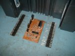
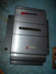
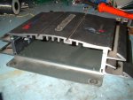
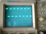
Well, since I can't do much with my LawnBoy until I get a new clutch and jackshaft, I started working on this project. I'm going to attempt to make a high power DC motor controller out of a cheap Chinese scooter controller, an old Radishack 50W amp enclosure and sixteen IRFZ46 N type MOSFET's. I was playing around with the motor controller today just to get an idea of how it works. It's actually a controller I found so I didn't know if it worked or not, turns out it does. The circuitry is very simple and I'm going to make a schematic of it for those of you who may be interested. Here's some pics of what I'm working with and a pic of the waveforms going into the gates of the MOSFET's at half throttle with the scope set to 1V/div.
 

Attachments

  • Power1.jpg
    Power1.jpg
    75.3 KB · Views: 96
  • Power2.jpg
    Power2.jpg
    67.2 KB · Views: 41
  • Power3.jpg
    Power3.jpg
    84.5 KB · Views: 36
  • Power4.jpg
    Power4.jpg
    52.7 KB · Views: 43

kibble

I banned myself
Messages
2,766
Reaction score
16
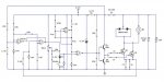
Well, I drew up a schematic. This is the basic controller, nothing beefed up yet and all components set for 24V. I'm hoping I got everything right.

From what I can tell on the schematic and from experimenting with it, I think the first section with OP amp #4 is a low voltage cut-off circuit that prevents the circuit from working if the voltage gets low enough, to prevent damage to the batteries.

The second section with amp #3, I think is a current monitor which cuts off the controller if there's a short or too much current being drawn. It measures the difference across the "resistors" I labeled J1 and J2 to check the current. From poking around with my multimeter, I think the threshold is 63mv, I stalled the motor and managed to reach 54mv at the negative input of amp 3, but because I wasn't using a full 24V, I wasn't able to trip it.

Amp #1 is the clock generator and makes a triangle waveform.

Amp #2 is the pulse width modulator and produces a square wave from the output of amp 1 and the throttle voltage. It then feeds into Q3 and Q4 transistors which drive the MOSFETs.

Q3 is 2N5551 and Q4 is 2N5401
Q1 and 2 are both BUK7520
MBR20100 is an AKA Diode in a TO220 package which prevents voltage spikes from the motor from damaging the circuit.

S1 is the ON/OFF switch.

The momentary switch labeled "Brake" is activated when you push on the brakes to prevent the throttle from working at the same time.

"Hall" is the throttle. It is a magnetic sensor that puts out 0-5V. 0V being closed and 5V being wide open.

All resistors are 1/4 watt, but can be 1/8 except for the 50Ohm, 1/2 watt after S1. The diode (D1) next to the brake switch is a generic diode like 1N4004 or whatever.

The 5.2V zener diode regulates the voltage to power the actual controller circuitry.

What I will be doing is basically adding more MOSFETS to the power section and change some things here and there to make it so it handles 36 volts. Well, I was thinking of maybe putting a switch on it which will let me select the input voltage and change values around accordingly.
 

Attachments

  • Controller.jpg
    Controller.jpg
    53.1 KB · Views: 304

zabac70

New member
Messages
64
Reaction score
0
Interesting :thumbsup: How many amps could it take (and how many it will handle, when you're done with it) ?
 

kibble

I banned myself
Messages
2,766
Reaction score
16
The IRFZ46N's I'm using are rated for 50A continuous, so I'm not 100% sure if I would just multiply that by how many I'm using (16), which would say that it's 800A. I'm not sure I believe that myself, it's probably some lower amount. :confused:
 

zabac70

New member
Messages
64
Reaction score
0
:) You'll be a very rich man soon. 800 A for under 100 dollar ??? Zilla (controller manufacturer ) will put a contract on your head :) You probably looking at 45 A - 60 A continuous if you heavily modify gate and other stuff (I'm not an electronic expert , so I couldn't tell), based on what I've read on the net in a past year or so. Heat dissipation alone will fry circuit and the casing if you put even fraction of that current trough it. See this please: http://zeva.com.au/tech/controller_design/
As I wrote , I'm not an expert , but I strongly suggest before you ruin a working controller , do a bit of research (yahoo groups: OSMC) and please report of the progress.
BTW (this is off topic) I've never had a chance to thank you about car starter motor stuff (pics especially) so : THANKS!
 

kibble

I banned myself
Messages
2,766
Reaction score
16
Hey, that's a nice page you posted, but that guy is also intending to use it in a car with a hardcore motor, not like something small, like I'm intending. I got some tips from that page though. Thanks!
 

zabac70

New member
Messages
64
Reaction score
0
Yeap , I know , that was a point. With 800 Amps and, say , 24 Volts you will have...wait for it...19 200 Watts (19.2 KW). Pretty darn good for a controller from a waisted electric scooter :). Strongly suggest to visit yahoo group OSMC (open source motor controller) - those gyes knows their stuff , and you can find there schematics , ask questions and find smart ideas (if you read it long and thorough enough). However, keep a good work :thumbsup:
 

kibble

I banned myself
Messages
2,766
Reaction score
16
Well, I'm hoping my controller will be able to handle a starter motor, which needs 12V, but I'm not sure how many amps. I'm going to put a switch on it that will let me select between 12/24/36 volts. I was also going to do 48, but that's getting too close to the limits of the MOSFET so I'm not going there. The main motor I'm intending on using is a 36V 500W I got from one of the other guys on here. I will also test my modified starter motors to see how it works out. Experimentation's the name of the game and I intend to push this thing to its limits, wether it holds up or goes down in flames (literally).

Zabac70, I'll definitely check out that group.
 

zabac70

New member
Messages
64
Reaction score
0
@stephenm2682
Well , in principal , the same as I've said before - try yahoo groups/OSMC. If you think of car starter as a motor like ones in battery powered tools (brushed DC motors), you basically need a giant dimmer (in terms of current) - just like the trigger on battery operated drill. Voltage depends on your choice - would you go as it is 12 Volts , or you want to overvolt it and go with 24 Volts. In eider case , you'll need something to limit the current trough controller , cause the easyest way to have "throttle" is PWM regulated device or "pot" (potentiometer). They usually operate in range 0 - 5 V (for purposes of light Ev's). Current trough this devices is measured (usually) in milliamp , so you don't want to hook up your battery pack directly to it. Therefore you need something to limit the current to the board (controller). Device (integrated into a controller) is called "bridge". Accept the internet (which sometimes can be confusing , cause highly professional people talking about something that we don't understand or know of, which is plane and simple to them), the best way is to talk to a professionals from electrical department "in the field": car electricians , guys who maintain forklifts (electric ones) or elevators (lifts)...Well , that is my approach anyway.
To answer your question directly : you need to determine few things - how many Volts will be in your system , how heavy is the vehicle you intend to build (so we can assume how many amps theoretically can "pull" from battery pack), how complicated (expensive) you want it to be. If you not familiar with electronics , you might as well to google (or e-bay) "controllers for brushed DC motors" and find what you need (I would look for ones with 40 - 50 Amps continuous rating, if it is for light vehicle) - they aren't very expensive.
And a bit of warning - I'm NOT electric/electronic expert (I was studying for machine/mechanic engineer) , so you should check everything I say (and English isn't my language). All the things I said I found on the net or it came from the professionals I've been talking to. Hope that helps.
 

zabac70

New member
Messages
64
Reaction score
0
Well, I'm hoping my controller will be able to handle a starter motor, which needs 12V, but I'm not sure how many amps. I'm going to put a switch on it that will let me select between 12/24/36 volts. I was also going to do 48, but that's getting too close to the limits of the MOSFET so I'm not going there. The main motor I'm intending on using is a 36V 500W I got from one of the other guys on here. I will also test my modified starter motors to see how it works out. Experimentation's the name of the game and I intend to push this thing to its limits, wether it holds up or goes down in flames (literally).

Zabac70, I'll definitely check out that group.

Does that motor have Amp rating on it(I mean that 500 W motor)? It can handle the overvolting , but not very well if you put more amps than it can handle (heat will build up and melt something , unless you provide extra cooling). I mean there is no need to overkill your controller if it isn't nessesary. As for car starter motor , I've been told that it pulls 70 -80 Amps(sometimes more) for a short period of time , during start of engine (depends of engine of course).
Do experiment , by all means , but don't waste components (save the planet :) ), that is why I keep quaqing about research :) :thumbsup:
 

kibble

I banned myself
Messages
2,766
Reaction score
16
Hey, no problem stephenm2682.

Zabac70 said in the other thread about the starter that a small starter motor was about 800W.

No, the 500W motor I have doesn't have an amp rating on it, the sticker is gone.

Oh, and BTW, I'm not going into this completely blind. I've built PWM power supplies before to use in my car and other things and just to play with. I've also built motor controllers for an R/C car I had that handled pretty well. My oscilloscope has helped me out a bunch in figuring out what's going on when things aren't working properly. I've just never built one for handling this much current before. :idea2:

I'm currently learning to program and soon, I want to be programming PIC's so I can use them in my projects. I have a couple of small learning kits and software that I've been messing with.
 

ed1380

Banned
Messages
1,182
Reaction score
1
Location
ATL, GA
never been a fan of pics. ive been raised on the atmega chips. around 4 bucks a pop and you can get away with a homemade programmer. the ide is also free
 

zabac70

New member
Messages
64
Reaction score
0
@stephenm2682
I did said around 800 W for car starter (for smaller cars); cca 70 A x 12 V = 840 W (for example). With car starter , what you really want is to double voltage and lower the current (less Amps) , cause lower current is easier to control (and less expensive and the battery will last longer) and car starters are pretty torqy stuff (they can move the car in the first gear).
@kibble
Sorry , I didn't meant to say that you don't know what you're doing, I was just posting my opinion and how I approach the matter (since I don't have the "electrical" background). And my English (construction of the sentence and spelling) could be somewhat confusing. Of course , your thread (about the car starter) was the one of the main reasons for me to join this forum:thumbsup:
Regarding programming , I don't really have the time (or will) to learn it, and if problem occurs that involves programming , I'll just post it here (or somewhere similar) or by a chocolate to allure some kids that knows the stuff (seems to me that they're born with that knowledge) and get the problem solved
 

stephenm2682

New member
Messages
164
Reaction score
1
so to lower currant thats where a pwm comes in? i think i'll stay with gas, an expensive route unless someone as a link for pwm?
 

zabac70

New member
Messages
64
Reaction score
0
http://tech.groups.yahoo.com/group/osmc/files/
This page have all the stuff that you need for everything that we've talked about and you should follow links on it. Schematics and theory and parts lists and pictures . Of course , you alone must decide what you'll use of it and is it worth wile, or is it simpler (very likely cheaper) to buy something from e-bay that is already working and you just have to mount it and connect it to the battery pack and motor.
Here are some links , but you really should try to google it yourself.
http://f-cpu.seul.org/~nico/astromech/motor_control/tipntrick_motor.pdf
http://www.nxp.com/acrobat_download/applicationnotes/AN10513_1.pdf
It is not that complicated to put together a simple and cheap electric drive system for light EV. If you use modified car starter , it could be done in a matter of few days and about 200 dollar(including battery pack). The main problem and the biggest part of financial expense are the batteries: LA are cheap and heavy , lithium are very expensive and light (and last few times longer and you can use almost all capacity).
If you decide to go with gas - well , have fun with it; I did what I could to help :)
 
Status
Not open for further replies.
Top