PWM Motor controller

Status
Not open for further replies.

kibble

I banned myself
Messages
2,766
Reaction score
16
never been a fan of pics. ive been raised on the atmega chips. around 4 bucks a pop and you can get away with a homemade programmer. the ide is also free

I've thought about Atmega's too, it's really difficult getting to learn stuff like this by yourself though. I don't personally know anyone else that's into electronics like this, other than one of my uncles, but he lives kinda far away and he doesn't do as much as he used to. All my friends are into other things so pretty much everything I know, I've learned by myself.
 

Scumm

New member
Messages
15
Reaction score
0
So, back to before the hijack... Kibble your project is really what i've been hunting. The closest controller Ive found is http://www.dimensionengineering.com/Sabertooth2X25.htm

but the rating is too low for my application. After finding 2 drills my landlord threw out w/ 1/4 HP motors, I've been thinking about making a kick *** radio controlled vehicle.
 

kibble

I banned myself
Messages
2,766
Reaction score
16
I need to start designing the circuit board for the controller. So far I have been collecting some components that I will need. I still need more diodes but I went to the store to look for them and they didn't have them.

I need to get some connectors too.
 

kibble

I banned myself
Messages
2,766
Reaction score
16
Here's some progress. I started designing the board.
 

Attachments

  • pwmboard.jpg
    pwmboard.jpg
    38.2 KB · Views: 60

zabac70

New member
Messages
64
Reaction score
0
:thumbsup: 
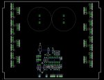
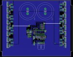
Is there enough space for heat sinks (I hope this is a correct term) on sides of the board. You should consider some kind of forced cooling for that number of mosfets.
 
Last edited:

kibble

I banned myself
Messages
2,766
Reaction score
16
The enclosure I'm using, the amp casing, is the heatsink and, yes, I was going to use a small fan to cool the inside of the case too.
 

kibble

I banned myself
Messages
2,766
Reaction score
16
Thanks! Here's some more. The stuff in the middle is the PWM part. I removed the zener diode and 1/2W resistor along with a few other things and am using a 3A, switching voltage regulator instead as I will be powering a few other things off of the 5V supply.

I added a connector that will be going to a 6 pin DIN connector on the case. The throttle and brake will connect to that and I may have a pin or two left for other things later on.

I will be making another sub-board that will monitor current and will have an LED bar graph to show battery voltage.

I'm still tweaking things here and there on the board so this is not the final design.
 

Attachments

  • PWM2.jpg
    PWM2.jpg
    58.7 KB · Views: 54

zabac70

New member
Messages
64
Reaction score
0
:thumbsup: When you finish it and test it with some load , will you post final schematics and board print (possibly parts list)?
 

ZnsaneRyder

Crazy Guy on a Bicycle
Messages
278
Reaction score
1
Location
FL
That's bad azz! You are making a new PCB and everything!!!

Sure beats using the RadioShack veroboards for sure!
 

kibble

I banned myself
Messages
2,766
Reaction score
16
:thumbsup: When you finish it and test it with some load , will you post final schematics and board print (possibly parts list)?

Yeah, once I make sure it works properly.

That's bad azz! You are making a new PCB and everything!!!

Sure beats using the RadioShack veroboards for sure!

LOL, I stopped using those radioshack boards forever ago. It's really not that hard to make your own boards with the photo etching method.
 

kibble

I banned myself
Messages
2,766
Reaction score
16
Here's a pic of a partial collection of some of the parts I'll be using. Unfortunately, progress is slow at the moment due to lack of funds.... :(
 

Attachments

  • components.jpg
    components.jpg
    73.4 KB · Views: 41

kibble

I banned myself
Messages
2,766
Reaction score
16
Finally made some progress today! :D

Got done etching the circuit boards that I'll be using. I will make another one that will monitor current but, that one hasn't been designed yet.

The big board is the main power board. the two smaller boards are; 5V regulator and a bar graph volt meter that I will use to monitor battery.

Here's some pics for your viewing pleasure....
 

Attachments

  • PWM05.jpg
    PWM05.jpg
    59.2 KB · Views: 34
  • PWM04.jpg
    PWM04.jpg
    56.7 KB · Views: 32
  • pwm03.jpg
    pwm03.jpg
    38.1 KB · Views: 16
  • PWM02.jpg
    PWM02.jpg
    42.5 KB · Views: 21
  • PWM1.jpg
    PWM1.jpg
    45.6 KB · Views: 30

truesprocket

Central Canadian
Messages
59
Reaction score
1
Location
toronto canada
looking to build a gocart size 12 volt motor controller,

Hi I'm looking to find scematic's to build a motor controller for a 12 volt golfcart style motor any help or site's you could point me to would be fantastic , I'm hoping to run it off 4 6volt deepcells, that'll depend on how long it lasts & I'd like to be able to switch to 24volts & push that through the 12volt motor, safe to do ? anybody ?
 

Attachments

  • DSCF9333.jpg
    DSCF9333.jpg
    74.3 KB · Views: 13
  • DSCF9341.jpg
    DSCF9341.jpg
    76.3 KB · Views: 8
  • DSCF9360.jpg
    DSCF9360.jpg
    126.9 KB · Views: 18
  • DSCF9357.jpg
    DSCF9357.jpg
    115.8 KB · Views: 15
  • DSCF9340.jpg
    DSCF9340.jpg
    101.3 KB · Views: 10

zabac70

New member
Messages
64
Reaction score
0
Cool stuff ... You can "push" doubled voltage trough your motor , but you have to be careful with power (Amps). As for schematic's , google is your friend , but I suggest Yahoo group : OSMC (open source motor controller) - you need to sign in. However , you need to do a bit of research first , to be sure what you want and need (controller wise) and have a look see on e-bay or wherever to check if something already exists that will suit you for the purpose - some of that stuff is really cheap and it is (often) not worth bothering to make one yourself (components you'll need , time and aggravation ...). Best of luck with your project !
 
Status
Not open for further replies.
Top