Newbie here. Rebuilding carter gx150IIr

Status
Not open for further replies.

Sandmanbjj

Well-known member
Messages
218
Reaction score
256
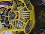
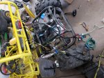
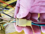
Wiring harness is being put in. This is a nightmare. I bought a harness from amazon and they dont have a diagram that tells you what each wire is for. I am slowly figuring each one out. But there are a bunch of splices on the kart that are hidden under a pile of electrical tape. So i basically have started ripping each wire out from front to back to make sure i get it wired in correct.
 

itsid

Moderator
Staff member
Messages
11,563
Reaction score
240
Location
Ruhrpott [Germany]
I feel for you..

Unfortunately I know no wiring schmeatic that you could rely on..
All I can dig up are more or less generic and while that helps to get an idea of what's what.
I bet you had the very same idea as well long before this post.

So yeah, all I can say is download as many gy6 wiring schematics as you can, from all the manufacturers and models you can dig up..
Do NOT concentrate on colors, just on connections and memorize them as good as you can.
then you can patchwork your own mental schematics when working on your kart.

(Or just print out all of them and have them handy when you work on it.. pick the closest feasible and use that as a hint [not necessarily as a guide though] )

'sid
 

Sandmanbjj

Well-known member
Messages
218
Reaction score
256
Ha. You hit my plan right on the head. I gave up on the color codes quickly. As the new wiring harness has only 1 or 2 wires the same. So i have been going by connection. Slowly.. taking notes as i go. As long as i am getting each connection the same as it was, there should theoretically be no issues. Lmao. I will see how that goes. Hahah.
 

Sandmanbjj

Well-known member
Messages
218
Reaction score
256
Running down each wire. Got most of it figured out. Now i have to line it all up, get it routed through the cart, and connect all the ends.
 

Attachments

  • 20190206_094116.jpg
    20190206_094116.jpg
    467.1 KB · Views: 4
  • 20190206_094127.jpg
    20190206_094127.jpg
    598.6 KB · Views: 5

Sandmanbjj

Well-known member
Messages
218
Reaction score
256
The front end is wired up. I opted to keep the ignition switch i had on the cart because the harness i bought had a 4 wire switch that i would have had to add a push button start. The one on the kart already was 6 wire and just a turn key start. So to keep it "simple" I just ran all new wire from my ignition, kill switch, light switch, head lights and brake switch to the back. One wire at a time to make sure they were being connected to the right thing.
Now working on the back, i had to cut open the protective plastic wrap on the harness i bought and make sure where all the wires actually went and that they were not spliced into different colors (more than 1 connection was that way).
It is tedious and slow. But its getting there. I do feel sorry for the next guy trying to figure out the wiring... because although i understand my color coding, it isnt in any book. Ha.
 

Sandmanbjj

Well-known member
Messages
218
Reaction score
256
I have a question that i hope doesnt make me look like a complete jackass. In fhe attached picture, i circled an inline fuse. This fuse is fine when i connect the battery. But as soon as i turn the key to the on position, not even to start, just 1 click. The fuse blows immediately.
I am thinking i may need to disconnect everything in the front and just do the ignition switch and then add in each component like the brake switch, the kill switch and then the lights.
My logic tells me i have a positive connected to a ground at some point when the switch is turned on it completes the circuit and this fuse luckily blows before i melt anything

Any suggestions?
 

Attachments

  • Screenshot_20190214-141716_Drive.jpg
    Screenshot_20190214-141716_Drive.jpg
    207.8 KB · Views: 12

FoulMouth

Member
Messages
37
Reaction score
2
Location
Tulsa
Do you have a muli-meter with a conductivity test? check conductivity between the B terminal on the key switch and the negative terminal of the battery. If your getting a reading or a beep, start unplugging stuff till you figure out what is grounding out or has a mismatched wire.
 

Sandmanbjj

Well-known member
Messages
218
Reaction score
256
Makes sense. Wasnt sure how i could check the conductivity. But this will be much easier than my first thought... and it sill save me a lot of fuses. Thank you!!
 

Sandmanbjj

Well-known member
Messages
218
Reaction score
256
I have dosconnected just about everything and still get a reading. I am stumped. Should i disconnect the positive terminsl from the battery also or leave that connected while i am checking?
 

FoulMouth

Member
Messages
37
Reaction score
2
Location
Tulsa
Yes, disconnect the positive on the battery, it shouldn't matter, but it could give you a false reading. checking conductivity or connectivity is simply checking that the 2 points are connect by a complete circuit. like putting the meter on both ends of a single wire to make sure its not broken in the middle somewhere. I took another look at your diagram and it looks like the black wires are the power wire from the key to the (CDI, flashers, Brake sw, HI/Low sw, LCD, horn SW and cigarette lighter. When your key hits the first position the black wires start carrying power. Either one of the black wires on a component is hooked to a ground path or a component is shorting out internally. My guess is either your key switch is grounding out or one of the listed parts has a black wire connected to ground.
 

Sandmanbjj

Well-known member
Messages
218
Reaction score
256
That helps tremendously. I know i hooked all my black wires to a ground at some point. Which seemed odd since my green wires from the same area are grounded.
Looking at the diagram i understand the basics but some of the symbols i am not familiar with so i am sure i got them mixed up. I really appreciate the suggestions. I will let you know how it has worked out.
 

FoulMouth

Member
Messages
37
Reaction score
2
Location
Tulsa
Does your harness follow the diagram fairly well? If so you will probably find it pretty quick, If the harness has different colors than the diagram you may need to do more multi-meter testing to get it all worked out.
 

Sandmanbjj

Well-known member
Messages
218
Reaction score
256
No. The harness is wired for some different stuff. The colors dont match, i dont have turn signals, a horn, or cigarette lighter. I am essentially rewiring it at this point. But i have done it by remove one and replace it. So it should be the same as it was.
 

FoulMouth

Member
Messages
37
Reaction score
2
Location
Tulsa
Thats a fun puzzle, fortunately you don't need much to get it running. Concentrate on the CDI box, coil, possibly the brake switch, and the start solenoid if equipped.

---------- Post added at 01:01 PM ---------- Previous post was at 12:45 PM ----------

Do the plugs on the harness match up to the plugs on the diagram?
 

Sandmanbjj

Well-known member
Messages
218
Reaction score
256
I will post a pic when i get home. But i have a question about the ignition switch wiring here. Coming out of the switch is 6 wires. I have most of it figured out, but the harness where a brown wire comes out of the switch, then plugs into the wire harness, the wire that matches up with the brown wire is black on the other side of the connector. And the black wire coming out of the switch is green/white coming out of the connector. Which color should i consider when am hooking up their respective areas? The one into the switch or the wire out of the connector heading to the rest of the buggy?
 

Sandmanbjj

Well-known member
Messages
218
Reaction score
256
There is some overspray on the wires but you can see coming out of the switch black and at the connecter it is green and white and brown at the switch comes out of the connector as black. Not sure which to use as my black.
The cleaner wires are the switch side. The over spray wires are to the buggy
 

Attachments

  • 20190219_135918.jpg
    20190219_135918.jpg
    227.3 KB · Views: 2
  • 20190219_135952.jpg
    20190219_135952.jpg
    252.8 KB · Views: 1

Sandmanbjj

Well-known member
Messages
218
Reaction score
256
Ha. It is only 5 wires in my switch. Black, red, green, brown, green/red. So i really just need to figure out what each wire on the switch is for, then i can connect it properly. My head hurts
 

FoulMouth

Member
Messages
37
Reaction score
2
Location
Tulsa
You can use the multi-meter to test everything. Test conductivity between parts on the harness. So put one probe on the black wire at the switch connector on the harness, and the other probe can check component connectors. The key switch should only operate in 3 modes, off, on and momentary on. You’ll test it by checking continuity at the input and all other connections, with the key in both positions.


Sent from my iPhone using Tapatalk
 
Status
Not open for further replies.
Top