Thanks Machinist@Large for your comments

.
Give me time to answer your questions. I left my design since the threaded rod broken. This weekend needs to replace the broken parts and requires some welding works.
I already purchased the parts to replace the broken part. Honestly speaking, I am new to welding and consider naive in metal works as well. That's why I chose threaded rod instead of other types of rods. However, my strong interest motivates me until competion of this design.
I found out that the threaded rod is not made of pure ion. It contains other stuffs as well. Probably that has caused it to break if carry heavy load and jerking. Do you agree with me on this? This advises me to select suitable materials for my design.
I think that there are several forces/ stresses that lead to the break on your cart; I'll list the ones I'm most sure of. Without the pieces in front of me, all I can do is guess.
1)Threaded rod is relatively weak in unsupported torsion loads. When it's not supported (threaded into a hole), it's first inclination is to:
A) twist itself into a knot, just like spring (when rotary force is applied in the direction of rotation) or,
B)untwist itself (just like a spring) when the force is applied in the opposite direction.
2) MOST threaded rod is threaded by rolling; the threads are not cut.( Think holding a pencil between your hands with just your fingers and roll it back and forth).
A) This means when you want to use it to support a load under tension you have to treat it as a smaller dia. rod (dia. of the base of the threads)
B) Because of the threads, it isn't recommended for use in compression distances more than 2 to 5 times the outside dia. of the rod.(When unsupported) You can help compensate for it by sleeving it or adding bracing.
3)Never weld a threaded member in the direction of load when used it tension-I.E. say, when you need to make your own bolts (load pulling on the weld). When you screw the nut onto the rod, only weld the top. If you weld the bottom, the load will be focused on where the exits the nut; not be evenly spread around the joint. If you are planning to weld a nut in the middle of a threaded shaft for an adjuster, use 2 nuts, jamb them together and weld the nuts together.
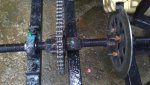
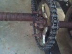
4)Looking at the picture of the break, I'm guessing if you look at it, you'll find a hard shiny area at the 4 points you tacked to lock the nut to the shaft. There may also be a dry, rusty powder. If so, that is called fret rust. It's caused by the 2 sides of the break rubbing together. these are signs of stress being focused at those points. You can still get them using smooth shafting, but it's a lot less common.
There are whole classes on all the different forces that can be put in play in any design; I'm just trying to share some of what little
Iknow about with you. Hope this was of help. Pat.

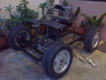 Photo 1.jpg68.6 KB · Views: 244
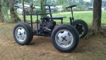 06082011870.jpg106.9 KB · Views: 103
 06082011864.jpg90.1 KB · Views: 115
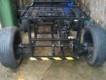
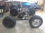
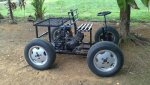
 and are those car tires?? What's the max speed on that?

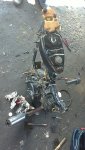
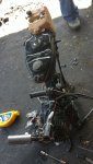

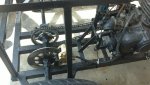
 Ouch!! Good thing you weren't hurt. That's one of the problems with threaded rod, especially where you welded the nut to it. I take it that this is the shaft that transmits power from the engine sprocket to both the rear wheels? Questions;