You are using an out of date browser. It may not display this or other websites correctly.
You should upgrade or use an alternative browser.
You should upgrade or use an alternative browser.
murray explorer project.
- Thread starter Dougthewelder
- Start date
- Status
- Not open for further replies.
Dougthewelder
New member
- Messages
- 163
- Reaction score
- 0
what is that? can you explain or post a pic?
http://chestofbooks.com/crafts/meta...orkers/images/Fig-116-Triple-Thread-Screw.jpg
That is a tripple pitch thread one turn turns it 3 times more then a normal bolt
That is a tripple pitch thread one turn turns it 3 times more then a normal bolt
mckutzy
Well-known member
finding something with that thread would be next to impossible unless a machinist made it, then again he would charge u and arm and a leg for it if he did make it for you. an acme thread from a c-clamp will do no prob, and it makes for easy adjustment and pad wear.
Dougthewelder
New member
- Messages
- 163
- Reaction score
- 0
yea a thread like that would be ideal freakboy but it would be better to make it out of easy to get parts imo.
Dougthewelder
New member
- Messages
- 163
- Reaction score
- 0
Dougthewelder
New member
- Messages
- 163
- Reaction score
- 0
so i have a 10tooth on my tav now and i wanted a bit more climbing power so i ordered an 8 tooth. what do you guys think? is this to few teeth on a sprocket? will it wear out to fast?
the guy i got it from says it was custom made, and i don't see them available anywhere else.
http://cgi.ebay.com/ws/eBayISAPI.dl...ename=ADME:B:EOIBSA:MOTORS:1123#ht_500wt_1182
the guy i got it from says it was custom made, and i don't see them available anywhere else.
http://cgi.ebay.com/ws/eBayISAPI.dl...ename=ADME:B:EOIBSA:MOTORS:1123#ht_500wt_1182
Dougthewelder
New member
- Messages
- 163
- Reaction score
- 0
Murray Explore First Project
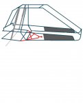
I really like the independent suspension with the sold axle... My project kinda began when i was in junior high and wreck my KD 175 street and trail bike but the motor was undamaged. So i started making plans and and started collecting thing but i really wanted something with a rollcage.... so about to years ago i bought a murray explorer off of a friend....Im now 20 years old and have worked on this thing on and off trying not to spend money.....so after seeing your idea i figured i would try it out...here's a blue print kinda thing of what im wanting to do... I would like to use the front shocks off of another bike I have for the rear and eventually make a front suspension later on.
Please let me know what you think and any proubles that might come about.......one worry is the backend shifting left to right or will the shocks take care of that
Attachments
-
 1.JPG44.8 KB · Views: 13
 -
![s[1].jpg](/community/data/attachments/4/4845-1ba6c20f44312df70bbbbc1cc4030dea.jpg) s[1].jpg79.3 KB · Views: 31
s[1].jpg79.3 KB · Views: 31
Dougthewelder
New member
- Messages
- 163
- Reaction score
- 0
so you are pretty much going to be doing the same thing i did with mine. it worked out great i think! you will need a cross link to stop the movement from side to side.

the red arrows point to the hinges. one side of the cross link must connect to the frame and the other needs to connect to the swing arm. i made mine curved to clearance the sprocket and brake assembly. just remember that because the swing arm will be able to move up and down as well as rotate make sure your engine and such will not collide with the frame. good luck and have fun!

the red arrows point to the hinges. one side of the cross link must connect to the frame and the other needs to connect to the swing arm. i made mine curved to clearance the sprocket and brake assembly. just remember that because the swing arm will be able to move up and down as well as rotate make sure your engine and such will not collide with the frame. good luck and have fun!
Doc Sprocket
*********
You've got some great ideas in there, Doug. In fact, while I was batting ideas around for my own mechanical caliper, I did think of the C-Clamp idea too- But I wasn't sure I could get a nut with the same thread pitch as the clamp screw. Is this possible, and what is the standard?
I also thought about the possibility of using a ratchet (socket wrench) handle as the actuator arm, with an eye towards a self-adjusting setup. With wear, sooner or later the arm's throw would cause the ratchet handle to click on the next tooth and re-tighten the caliper. It works in my head, anyhow...
Also- I'm quite interested in your rear suspension, having tossed similar ideas around. What did you use for the big ball joint? I was thinking of maybe using a 1 7/8" Trailer ball and coupler. Redneck maybe, but this too works in my head...
EDIT- I just spotted the point in the one video, where I can clearly see the Heim joint you used. Cool! (Still like the redneckish trailer hitch idea, tho'!)
Comments? Cheers- Chris
Last edited:
Dougthewelder
New member
- Messages
- 163
- Reaction score
- 0
red neck ideas are sometimes the best. the ball joint i used is actually half a tie rod for a tractor so i think that qualifies as red neck!
the ratchet idea is intriguing to me. i wonder how you would keep it from tightening up to much. it would need some kind of spring return in the right spot to make it work right. as far as finding the right threads, i was just going to take apart a C-clamp lol.
the ratchet idea is intriguing to me. i wonder how you would keep it from tightening up to much. it would need some kind of spring return in the right spot to make it work right. as far as finding the right threads, i was just going to take apart a C-clamp lol.
Doc Sprocket
*********
I haven't had an opportunity to play with the concept yet, but I think it could work. A typical ratchet has what- a 5* sweep? I'm fairly sure that 5* is enough travel with a coarse thread like a C-clamp. The whole concept rides on the notion of the arm NOT exceeding that 5* travel under braking/ releasing operation. You'd need a return spring on the arm for sure. Where it gets interesting, is the spring action on the "drive" side of the ratchet, where it attaches to the screw. Instinct says to put a return spring there, but I think that may be wrong. You know when you're driving a loose bolt, and you have to put your finger on it to apply a little tension to keep the ratchet going? I actually think a light spring pulling in the tightening direction is in order. Not enough force to cause the pads to really drag, but enough that the screw won't back off when the arm is released. Then, as the pads wear, sooner or later the screw will rotate enough for the ratchet to engage the next tooth.
I think...
I think...
modelengineer
Lord of the noise
That's not independent suspension, when one wheel moves so does the other...
Dougthewelder
New member
- Messages
- 163
- Reaction score
- 0
That's not independent suspension, when one wheel moves so does the other...
it is independent in that the wheels can move up and down independently. in contrast many go kart designs have the rear of the kart hinge like a swing arm, causing both the rear wheels to move up and down together.
http://www.youtube.com/watch?v=dDkzJ1nbRTI
Kenny_McCormic
Kartless....
it is independent in that the wheels can move up and down independently. in contrast many go kart designs have the rear of the kart hinge like a swing arm, causing both the rear wheels to move up and down together.
http://www.youtube.com/watch?v=dDkzJ1nbRTI
Maybe so, but in the automotive world, that's still a solid/live axle. With IRS the movement of the two wheel is independent, in your design there is still influence, just more freedom(which I do give you credit for!). My car has four wheel independent suspension, I will take a pic tomorrow if you want.
Dougthewelder
New member
- Messages
- 163
- Reaction score
- 0
lol, i know what fully independent suspension is guys. =)
my goal with this design was to relieve torsional stress from the frame and allow some articulation for uneven terrain. a lot of go karts seem to rely on the brute strength of the frame to deal with these issues.
fully independent rear suspension would have been annoying and expensive what with all the cv joints and such.
nerfo
New member
Doug, I gotta say... these are some phenominal ideas! I love your brake caliper, your half a tractor tie rod... umm, suspension attachment point thing (Which I think is freakin AWESOME!) Even your panhard bar has geometry that's almost spot on! I mean, for one beat-the-f-up looking go kart, it's probably one of the more innovative ones I've ever seen! Although, my favorite part of this whole thing, is the multi-spring, four (five?) link front end! Drop the K out of Kart, and you have what this truly is...
Doc Sprocket
*********
Yeah, I like it a lot too- I am planning something quite similar for the rearend. No folks, it's not "independant" according to definition, but it does articulate, which is excellent, and just what the doctor ordered for offroad. I agree that a true IRS would be too much of a hassle for most of us, and probably bring the budget out of reach. I have to admit I didn't pay much attention to the frontend, I was too busy bouncing the rearend and brake off my own ideas. I have a few different frontend ideas that stray away from your typical a-arm setup, and one idea looks alot like Doug's, being a beam axle, with a Ford truck style coil and radius arm arrangement. Another idea I was working on was a long crossover arm thing, where the right side suspension arm starts on the left frame rail, and vice-versa. I've seen something similar on offroad race truck, but the steering geometry was giving me fits. Can't figure out how to do it without major bump-steer. Ack! Too bad, it would have some great travel.
Doug, you ARE planning on putting a roll hoop or cage back on that thing, right? It'd be a real shame to grind that innovative brain of yours into paste!
Cheers- Chris
Doug, you ARE planning on putting a roll hoop or cage back on that thing, right? It'd be a real shame to grind that innovative brain of yours into paste!
Cheers- Chris
- Status
- Not open for further replies.