Possom Point
Well-known member
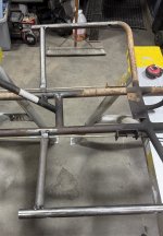
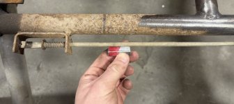
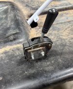
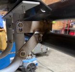
I drilled out these Manco spindles to “retrofit” them to this frame as well


So the spindles on the go kart truck were 5/8” and on the Manco they were 1/2”, I drilled the manco’s out to 5/8” to fit up to the truck and being able to use 4x4 spindles.Great updates to this magnificent build thread.
What’s the new spindle inner ID?
I wonder if the spindles were drilled out after the Zerk fitting was tapped and added (*at the factory). That has been bugging me with an ‘analysis paralysis’ on Zerk thread length, how to get the inner portion to have zero interference with the kingpin/spindle bolt or having the threaded end of the Zerk with the proper concavity…. I consider greased spindles a necessity.


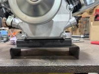
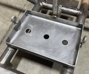
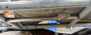
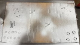
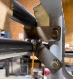
It’s 1/4” steel I cut on a laserThe bracket material looks really nice and 'factory'. How did you make it?
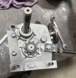
By the way, is that a drain bolt for the gearbox above the "down" (*3rd pic)?
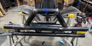
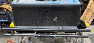
 . Trying to make thing look good along the way.
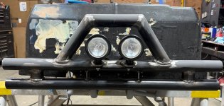


This was a very different build for me, most karts or mini bikes you can take apart and work on, this one has not been that way, I guess it was a custom type kart but not being able to take things apart to change or fix sucks.Nice work and smart planning for the future to make things easier for maintenance and repairs. Work smarter not harder!

")