You are using an out of date browser. It may not display this or other websites correctly.
You should upgrade or use an alternative browser.
You should upgrade or use an alternative browser.
Mario Kart Update (aka DuroPower)
- Thread starter snowjob
- Start date
Denny
Canned Monster
That is exactly what I was thinking. In fact you could even make it a little longer (think tunnel ram).
madprofessor
"Loose Cannon Creations"
If I understand it correctly, short free intake tubes are for best torque, and long "ram" tubes are for best horsepower curve.
I'll posit that the Predators benefit most from maximum free airflow intake. My effort would be to oversize the intake passage to the venturi as large as possible, for free flow to the venturi the way its curves were engineered to operate.
I'll posit that the Predators benefit most from maximum free airflow intake. My effort would be to oversize the intake passage to the venturi as large as possible, for free flow to the venturi the way its curves were engineered to operate.
snowjob
Member
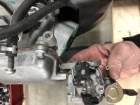
As with all projects....that took a bit longer than anticipated! First we got sidetracked by relocating our deck stairs, which became a partial deck rebuild. Then the aluminum Mikuni intake arrived and it required rotating and modifying the flanges. I attempted to use my TIG, but it quickly became apparent that cast aluminum is not the best material to learn TIG on. I then started fab out of steel and it went pretty well. I didn't have the right electrode & fill rod for the TIG, so I hacked it together with my MIG and lots of precision grinding ;-)
Now my son is off to Scouts for the weekend and we'll see how the exhaust progresses. I ordered the right TIG parts, so I will likely wait until they arrive next week.
Oh, and he really wants a 1970-72 El Camino project car. If you know of any cheap ones lying around in the midwest, just let us know. Decided it has to be a big block too....lol.

madprofessor
"Loose Cannon Creations"
Very cool extension manifold for hand-built. Some paint would likely be able to pass as store-bought.
Hoping someone with more knowledge about fuel atomization than myself will weigh in on that extension. Wondering if it means getting better fuel misting and uniformity during that passage than the factory dump into the head.
I still struggle with the idea that the heads' intake ports shouldn't be polished like the exhausts' ports. Something advantageous about disturbing the mixture's flow.
Denny
Canned Monster
Does a better job of mixing the fuel by keeping it tumbling and not allowing the fuel to fall out of suspension.
madprofessor
"Loose Cannon Creations"
Okay , think I get it, backwards thinking. The disturbance is more about preventing the DEatomizing of the mixture than to help CREATE the mix.
Seems that effect would be in play at low rpm, and fade to no effect at high rpm.
Seems that effect would be in play at low rpm, and fade to no effect at high rpm.
Denny
Canned Monster
Create the mix at slow speed. Keep it in suspension at high speed.
madprofessor
"Loose Cannon Creations"
Yes, that's the way I'm seeing it. Disturbing friction at low rpm, going by too fast to be affected at high rpm.
Denny
Canned Monster
By the way it looks like you did a good job on it.
snowjob
Member
Thanks guys. I can really tell I will enjoy learning TIG. It is just the type of challenge I enjoy. I may never get great at it, but the goal is a nice smooth weld. Using a foot pedal is a real change and it amazes me how you can really control the arc & heat with just the pedal. Welding the flange to the pipe was difficult due to different thicknesses, but if I can get the hang of welding the tube alone, there are lots of custom exhaust projects I have in mind.
snowjob
Member
I know it is hard to visualize a 3D shape in 2D, but this is the rough layout I am planning for the exhaust. Disregard the oversize straight pipe, it is just there until I cut the longer one.
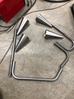
Essentially the header pipe splits 1:2 and drops from 1.25" to 1". The left side pipe does a U turn down, around and outside before terminating in two Mario Kart cones. The right side pipe turns 90 and drops behind the seat at an angle, turns 45 to be parallel to the ground before turning 90 toward the rear and around the engine. From there it splits to the two Mario Kart cones so they mirror the other side.
My biggest question right now is the 1:2 splitter. I don't know if I want them side by side or stacked vertically. I also don't know if a simple racetrack oval transitioning to a round is what I want (I have made one before) as this splitter will be on display on the top side of the engine. It's a shame I could not buy one, but I just couldn't find it in the sizes we are working with.
Once it is all fabbed I will worry about supports, finish, etc.
madprofessor
"Loose Cannon Creations"
Last time I made up a 2-into-1 transition in something the single piece (copper) was an oversized fitting at the join. I squeezed it in the middle to make complete contact, leaving a bowtie-looking opening for the 2 smaller pieces.
Silver-soldered the pinch together, and part of the bowtie on each side while access available. Then stuffed in the 2 smaller tubes and finished out the join so everything was pressure-tight. (All on the "bench" where the job was.)
Believe I used a reducer on the single piece after putting the assembly in place to get down to objective size.
If you have a torch and know how to solder, you can just flow the solder to the heat where you otherwise can't get access to weld.
snowjob
Member
Getting closer. I am pleased so far. Only a couple tacks & cuts to get to this point. This pipe is massively thick, so I am not too worried about welding it, even with my MIG. I am still debating the 1-2 transition, but I now I have plenty of tiny sections to do some tests with. If you see the black line where the two pipes split, that is the current end of the 1-1/4 pipe now so I could even splice them like a proper collector.
I can almost hear it

I can almost hear it

madprofessor
"Loose Cannon Creations"
Just remembered watching a custom exhaust build on one of the hotrod shows I watch, 5-6 of them, always one on at any given time.
They were doing a X-pipe, which has mostly gotten preference now over the older favorite, the H-pipe. They sliced off one side each of 2 only slightly bent straight pipes, sliced off the outer skin of the bends, welded the openings together, then continued the separate tubes.
The X-pipe idea isn't of crossing the pipe directions, but rather just letting them be freely together for a second. Helps with scavenging. Maybe some kind of angled slices like that could begin the 2-to-1 transition you're debating.
snowjob
Member
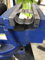
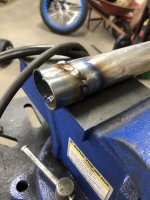
Think I am gonna be just fine. I went a bit overboard sketching this out, but flattening the 1-1/4 and cutting the sides off the 1.0 worked well. The 1.0 is even .110 wall thickness, so I have no breakthrough issues with the MIG. The 1-1/4 is only .090 wall thickness, so I need to allow cooling time after short welds. Didn't bother to clean up this test piece.





Denny
Canned Monster
It works for me.
madprofessor
"Loose Cannon Creations"
Man, you're on the sluice. That's exactly what I was talking about, and you're making it look good too. Success is in your near future.
snowjob
Member
It's starting to come together -
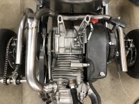
We are debating hanging it with a strap supported off the rocker cover or holding it up with something on the rear axle. My son made a new lever for the throttle, so he just needs to relocate the cable now.
Also looks like our local track of Danica Patrick fame allows run-what-you-brung testing. My son has asked for track time for this kart for his birthday. Calling today to figure out the details.
madprofessor
"Loose Cannon Creations"
Me want lurn weld lyke dat! You're right to debate hanging or supporting the weight, it would crack the header pipe.
Attaching before/after pics of how the weight of my steel silencer box is supported. It's wrapped in 2" wide fiberglass header wrap, so there's no rubbing or rattling steel on steel. The weight rests almost completely on the back 1.5" square tube of the motor rack.
The exact length of the header tube was devised by setting the bare steel silencer on the rack with 2 layers of the fiberglass under it to simulate exactly how high the silencer would be. The header tube comes down and penetrates a matching hole in top of the silencer, and continues almost to the bottom inside of it. It's sliced at an angle inside that allows free exhaust flow. Sat there loosely with silencer weight on the rack, then header tube was tacked in place the way it sat, weldout afterward.
The bolt head under it in the center is a threaded rod all the way to the front motor mount bolts, acts as the chain adjustment that slides the motor back and forth. Weight of the silencer stays evenly in contact with the motor rack as the motor slides, so it's always supported.
Figure for that movement when deciding best way to support your way cool and clean exhaust setup. Mine's built for about 4" of motion if desired.

