Manta motor controller issues

Status
Not open for further replies.

Functional Artist

Well-known member
Messages
5,645
Reaction score
3,281
Location
Toledo, Ohio
Wow!

All that's needed just to hook up the :censored: meter?

Is this a go kart or the space shuttle?

:huh: OK, tell me more.

Please explain, in detail maybe even throw in a diagram or pic. :thumbsup:
 

itsid

Moderator
Staff member
Messages
11,563
Reaction score
248
Location
Ruhrpott [Germany]
meter? noo just for the fan :D

I'm sorry, ...
honestly IYAM a powerline directly from one battery and a small switch (manually toggle) will do just nicely;

But sure.. a diagram... let me quickly mock one up...
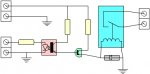
simpleoptocoupler_01.jpg

Sorry for the crappy layout, but I can't seem to find most parts in eagle; sooo I was quicker with a drawing tool :(

Now, yellowish parts are resistors ( left to right... 680, 33, and 150 Ohm)
the pinkish part is the optocoupler (that isolates the trigger circuit from the power circuit Vishay SFH617A-3)

greenish transistor A fairchild BC547B

the blueish relay (still a Sanyou SRB-S-112-DM)
with just a little diode for good measures (grey) say a 1N4936...

I think that should give you the ability to switch the relay with 3V 5mA signals...
Oh terminals... sorry..
upper left: 12V Power
lower left: Signal (3-15V)
right: switch.. whatever the relay can handle (say another 12V line for the fan in Question)

Now, it gets even better... I googled for a relay module with said Sanyou relay and the SFH617 optocoupler...
And I fricking found EXACTLY what I had in mind.
So since those minds are likely smarter than me.. I took their resistor values and diode as well as transistor specs
(frankly.. I think I couldn't have come up with decent values myself)

Anywas.. soldering required.. all parts incl the PCB ~$3 plus shipping :(

http://www.pollin.de/shop/dt/NTU5OT..._Module/Bausaetze/Bausatz_Relaiskarte_K1.html

cool huh?

'sid

PS I'm a bit baffled how close I was to the real world part...
I must have seen that earlier and forgot or something... weird!!
 

Functional Artist

Well-known member
Messages
5,645
Reaction score
3,281
Location
Toledo, Ohio
Impressive!

Seems a bit much just to run a fan but, very kool! :thumbsup:

Still workin' on gettin' this thing wired up.

Wow! This is complicated!

Knee deep in wires & several soldering iron burns later, I wonder, what did I get myself into? :rolleyes:

Still pluggin' away!

Workin' on the 36V power supply to key switch now.

Is it best to hook it directly to battery?

or hook to power cut off switch inside control box?

I am thinkin' that way when I cut power to batteries it cuts power to key switch also.
 

itsid

Moderator
Staff member
Messages
11,563
Reaction score
248
Location
Ruhrpott [Germany]
sure it looks overly complicated, but really it's not: a transistor to make a small signal a bit beefier and using that as a trigger for a relay that's in essence all there is to it.
the optocoupler is just a protection, and resistors are used to level the input according to the modules used..

Anyways, that's why I said manual toggle switch is likely easier (as long as you do not forget to actually use said switch)

the key (as in "start on off key") should be wired to the controller NOT the batteries.
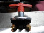
the Kill key (beefy master switch thing you have mounted to the controller box) should disconnect the batteries.
simple reason.. the key switch cannot withstand the amperage you would draw from the batteries.. so it could easily either burn or weld shut.
so the kart is either always on or always off until you replace the switch again ;)

'sid
 

Functional Artist

Well-known member
Messages
5,645
Reaction score
3,281
Location
Toledo, Ohio
I guess you misunderstood me.

I am talking about the 36V power source to the key switch that turns the controller & contactor on & off.

On the diagram it goes from the bat pack, thru a fuse, (to supply power in) to the key switch.

Switched power then goes (out) to the contactor & the speed controller (J2-2).

I know the power cut off is a "big" switch that we use to cut the power to the kart when not in use.

My question is..

Is it necessary to draw this 36V power straight from the bat pack or can I hook it up to the (out) side of the power cut off switch?

* Kinda like this...

A battery cable goes from bat pack to the cut off switch. (in)

A battery cable goes from cut off switch (out) (this is where I want to connect my 36V power draw) to the contactor. (in)

A battery cable goes from the contactor (out) to the speed controller. (B+) & to the (+) terminal on the motor.


This way I can keep the connection inside the control box & when I cut the power (big switch) it cuts power to that circuit also. :2guns:
 

Attachments

  • SAM_1333.jpg
    SAM_1333.jpg
    304.8 KB · Views: 4
  • SAM_1396.jpg
    SAM_1396.jpg
    220.2 KB · Views: 0

itsid

Moderator
Staff member
Messages
11,563
Reaction score
248
Location
Ruhrpott [Germany]
Ahhh I see.. doesn't matter really.. the fuse will take care,
but IYAM I'd wire it so that the powerswitch does what it's meant to do... i.e. cut off ALL power!
means wire the key switch from there.
(in that diagram that out terminal of your kill switch is the positive of the battery... to put it simply ;))

'sid
 

Functional Artist

Well-known member
Messages
5,645
Reaction score
3,281
Location
Toledo, Ohio
Yes, that was kinda my intention.

Power cut off switch, cuts off all power. :thumbsup:

Well, almost all power.

(The 12V for the fan will run directly off of (1) battery in the pack)


Yes, your right!

the diagram does not show/include the power cut off switch.

(we added that later)

Sorry, should of made that clearer. :eek:

so ya, as you said "(in that diagram that out terminal of your kill switch is the positive of the battery... to put it simply )"

Yup, that's what i'm talkin' about. :2guns:
 
Status
Not open for further replies.
Top