Manta motor controller issues

Status
Not open for further replies.

Functional Artist

Well-known member
Messages
4,411
Reaction score
1,694
Location
Toledo, Ohio
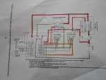
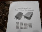
I have read the Kelly KDZ Series/PM Motor Controller User's Manual several times. (as you suggested) :thumbsup:

I even printed a copy so I could study the wiring diagram better & make notes.

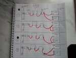
I also made several copies of the wiring diagram, so I could use different color markers to high lite the different circuits to help simplify the wiring layout.

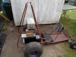
For this kart, I would like to stick with the 36 Volt set up.

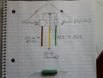
Here is the components I have in mind:

1. Kelly KDZ72550 Controller.

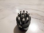
2. I already have a "standard" 36V contactor but, would probably be better off going with a beefier one like a 36V/400A.

3. 500 Amp fuse - main power line

4. 30 Amp fuse - key switch

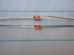
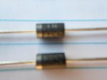
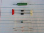
5. 3Amp/400V Coil Suppression Diode

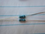
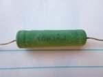
6. 220 Ohm/10W Pre-Charge Resistor

7. PB-6 (pot box) (x 2) 1 for throttle & 1 for Brake

8. Thermisistor

Is the Thermisistor necessary or an added safety feature?

Can a thermosistor be hooked up on this motor (overheat sensor not functional on this model) or does the overheat sensor need to be functional first.

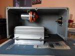
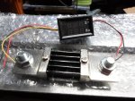
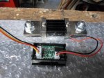
Is this what you had in mind for a control box?

http://www.alltraxinc.com/images/Heatsink_Assembly_400A.jpg

> Fuse Holder Main Battery (250 & 400amp)
> Logic Fuse holder for Key Switch & Controller Logic Power
> Main Solenoid (contactor) disconnect switch
> Bus bar connecting solenoid to fuse source
> Coil Suppression Diode (for solenoid coil)
> Pre-Charge resistor (Across main terminals)
> Auxiliary Relay for DC-DC Converters (KSI Controlled)
> Mounting surface for Alltrax 300amp, 400, 450, 500, 600,
and the venerable 650 amp controller

Material: Aluminum plate approx 3/8" thick (9.5mm)
Size: 10.5" x 10.5" (267mm x 267mm)
Part Number: Alltrax KIT-HEASTSINK-10x10

Not this specific one but, that concept, or an actual box?
 

Attachments

  • SAM_1335.jpg
    SAM_1335.jpg
    251.8 KB · Views: 5
  • SAM_1333.jpg
    SAM_1333.jpg
    304.8 KB · Views: 10

itsid

Moderator
Staff member
Messages
11,564
Reaction score
116
Location
Ruhrpott [Germany]
So,

the keyswitch itself will not see anything like 30 amps.. I doubt it's more than one tbh...
So a 2Amp fuse there should do to prevent it melting (but it depends on the switch what it can take)

the precharge resistor -as I said- should be in the realms of 1kOhm and beefy (10Watts)
220 ohms are just not enough IMHO;
and if you look on the far right in the diagram.. kellycontrols agree to that (couldn't made a better guess :D)

personally I don't like potboxes (don't ask.. just a personal thing I guess.. nevermind)
but they work fine if kept dry and clean, so pick a sealed one or find a cover for it.

The rest seems fine;

the thermistor is nothing really.. it's a tiny glass bead with some wire inside,
it'll change it's resistance when it heats up;
that's all there is to it.

I can't tell what type of thermistor the controller is able to read and what type of control you have over when it'll trigger to shut the motor down.
there are NTC and PTC thermistors (ntc reduce the resistance when getting hot, ptc increase resistance)
which one will work with the controller I can't tell (isn't that covered in the manual?)

but in the end it's a small glas bead that you can just epoxy to the motor case;
temp setting should be discussed with motenergy I can't tell what will be needed..
(I can only guess you're perfectly safe at ~100°C)
and hook it to the controller; it's seperated from the motors temp sensor
(which I assume is also just a thermistor epoxied to the motor coils originally)
if it's still in place and just disabled (not removed) and you can still hook into that;
it'd be perfect.
that temp reading inside is much more accurate.. it's just that you shouldn't mess with the motor internals on your own IMHO;
one mishap and the motor is a paper weight.

Anyways, that's too a question motenergy might be able to help you with.
UNfortunately I can't (I'd need to pop open your motor.. from here that's a bit difficult ;))

No with control box I meant more like a miniature dashboard to hold some LEDs and switches for your convenience.
Basically all the thingamabops you see on the far left of the wiring diagram;
plus maybe a battery indicator, a dead stop switch (cutting the throttle signal and shorting the brake signal)

And I'd add a huge battery switch somewhere near the batteries
(to stop creeping currents in the chassis in case everything is soaking wet)

talking about wet:
I'd have everything at least splash proof!

I mean frankly one puddle is enough to short nearly every electric part on a kart;
and you wouldn't want that..

so unless you can guarantee you're not seeing any water with that kart make it as waterproof as possible (splashproof at least)
So yeah, closed box IYAM.
otherwise you'll need to seal each contact and terminal seperately (which in itself is a good idea anyways)
but you know, this is a safety concern... totally up to you; but make sure you stay alive and so basically anyone that ever touches the kart in the end. ;)

'sid
 

Functional Artist

Well-known member
Messages
4,411
Reaction score
1,694
Location
Toledo, Ohio
so many questions, I have. (that's my Yoda impersonation) ;)

Yea, I know. I will stick to my day job. :backtotopic:

With my research & your advise, I felt comfortable enough to order the kdz72550 controller, a 36V/400A contactor, a 500A fuse, a thermisistor & an optional heat sink directly from from Kelly Controls.

I didn't see where they carried the diodes, resistor or pot box.

The best deal (good deal & seems to be quality, not just cheapest) I have found for these type items is from EV Drives. http://www.evdrives.com/category_s/1817.htm

I noted in earlier posts you mentioned the possible use of a thumb throttle & your opinion on pot boxes.

I would be interested in your thoughts on this subject.

Pot box vs. Hall effect or other. (before I make a decision & order these parts)

Another question I have is about the B+ connection.

The diagram shows that the B+ cable connects to 3 different components. (contactor, motor & controller)

Is there a best or proper way to accomplish this? I can see 4 different possibilities.

I would think #1. (see pic)

I have more questions but, will only ask a few at a time. :thumbsup:
 

Attachments

  • SAM_1333.jpg
    SAM_1333.jpg
    304.8 KB · Views: 7
  • SAM_1375.jpg
    SAM_1375.jpg
    241.2 KB · Views: 7

itsid

Moderator
Staff member
Messages
11,564
Reaction score
116
Location
Ruhrpott [Germany]
My reluctance against pot boxes...

Well hall effect sensors are magnetic field sensors and by design they're waterproof, or say uninfluenced by humidity) most come with epoxied or plastic cast sensor modules (for structural integrity more than humitidy reasons)
but still they're sealed units off the shelf. as long as the connectors kept dry, they will not fail when wet.

Pots are different.. most pots you'll find on the internet are open pots and not watertight at all and very very sensitive to this one stray drop of rain...
(on golf carts they sit sealed away and thus this is perfectly okay... on a go kart in the "open wild"... you know... not so much)
And this is frankly the only reason why as a throttle signal on an EV .. I'm not a fan (more hassle) nothing more to it.

Yes, you can use thumb throttles (or twist throttles as well)
take a typical thumb throttle for example:
https://www.motiondynamics.com.au/hall-effect-thumb-throttle.html

Mounts to a bar (you have quite a handfull on a kart ;)) but since it's not splittable you can just fab a holder with a very short bar on it to fix that to the floorpan.
the small lever is plastic and can be drilled to take a small connecting rod from the pedal itself
std Manco pedals and digital signals.. 13 bucks.. not bad huh ;)

But here's an even better solution IMHO:
https://www.motiondynamics.com.au/pull-throttle.html
std issue bowden cable for std issue pedals.. couldn't get any better IYAM. (11 bucks)

Now wiring.. all four are technically identical..
But yes, #1 is indeed my favourite
what you want is two things:
all connections as short and beefy as possible (least amount of resistance)
the least amount of open terminals (that'd exclude #4)

But if you can shorten the overall length of wires by a noteworthy amount using any other option it'll be fine.
As long as you make sure that each wire to wire connection is as good as possible
(so better use one crimp connector for both wires and solder to fill in possible gaps)

No necessary it is not young padawan (and here's mine :D)
but it'll help to reduce overall wire resistance (a pain to fix if one breaks though)

Ahhh you have seen what I just saw?
Kelly defaults to a KTY84 thermistor... 130°C cool, huh?!
http://kellycontroller.com/kty84-130-thermistor-p-314.html

A 1kOhm resistor will be easy to find to read it properly.

talking about 1kOhm resistors..
http://www.elv.de/vishay-drahtwider...id=SEM_30003&gclid=CNCzo8mk5c4CFdUaGwodJXMGpw
these are nice ...
unfortunately I cannot find a similar one on the googles (throwing me back to german results all the time)
found one for 8bucks on amazon.com (ohmlite) :(
https://www.amazon.com/OHMITE-810F1K0E-RESISTOR-WIREWOUND-1KOHM/dp/B00MNC1PVG

but cooling case is a nice idea for a precharge that size. ;)

And no, kelly doesn't have diodes or resistors listed,
but you can find them at radioshack or farnell or digikey or... any electronics store really ;)
(or amazon or ebay or alibaba for that matter)
or here:
http://www.evdrives.com/product_p/kit-csd-3.htm
http://www.evdrives.com/product_p/kit-pcr-1k.htm (will work.. not a fan though)


Somehow there's also no potbox listed anymore..
but it's been a PB8 (or PB6) AFAIR just google PB8 Potbox and you'll find several.
uhm..
http://www.evdrives.com/product_p/thr-pb6.htm (OUCH!)

'sid
 

Functional Artist

Well-known member
Messages
4,411
Reaction score
1,694
Location
Toledo, Ohio
Those Hall Effect Pull Throttle cables are a super solution! :thumbsup:

Lower cost, digital, water resistant & a simpler set up. All pluses.

I would have never found them.

Thanks for the tip. Your Awesome! :2guns:

I would think they could be used for both the throttle & brake signal to the controller.

What about the micro-switch's that are in pots & shown on the wiring diagram? Are they necessary?

Yup, I like the thermisister too. :wai:

Should help keep me from killing it too soon.

Is the 1 KOhm resistor used on the contactor the same as the 1KOhm resistor used in the thermisistor circuit? (just order 2 of the same?)

Is an emergency kill (big red button) switch necessary if there is a key switch on the dash board?

I have been looking at gauges for the dash.

Will this work?
http://www.ebay.com/itm/DC-300V-500...663307?hash=item2c828a4f0b:g:A90AAOxypNtSnjUf

What would you recommend?
 

itsid

Moderator
Staff member
Messages
11,564
Reaction score
116
Location
Ruhrpott [Germany]
I think these pull throttles are definetely splash proof, to be completely waterproof I'd miss a silicone lip ;)
But yes, it'll be fine.

I think you could also use it as a brake signal, it's worth a try.

I do assume the kelly will work with a three wire hall effect throttle..
unfortunately they only call wirecounts for potentiometers not hall effect throttles.
The potbox in the diagram is just that a 0-5V regualted potentiometer with activation microswitch (toggles when moved out of resting position)
There is no need for such switch in most cases.. some controllers still want them, others accept them and if not present will still work fine.
I can't tell tbh.
at worst you can just add a tiny switch that'd be toggled by the cable end and add the two more wires that way though.
I bet that bore you see on the exploded view matches up just nicely with the cable end in rest... and may even hold a tiny tactile switch (4.5 or 5.5 diameter)

Oh one thing: I've seen the pull throttle has a max travel of 20mm (not even an inch) so you'd need to connect it really low on the pedal for a good travel of the pedal itself.
just saying ;)

No, the 1kOhm resistors are not the same (well not necessarily)
You do not need anything like 10W to read the thermistor... not even one watt.
A foil resistor (20cts) will do.. but sure.. if you want you can hook up another 10W without problems if that makes it easier for you.

No, an emergency switch is NOT necessary.. but in case you let someone unexperienced with your kart ride it.. it's nice to know there's an obvious big button to turn off all the madness.

it's easier to hit the button when you panic than to turn a key,
or say soothing to have a button to hit, if you break the key and panic because of that ;)
if you want this neighbors kid to have a go, you want to know he'll be safe as well, right :D

OHHH WAIT!!
YES! it IS necessary.. Contest's rules say
6) Must be "complete" by deadline date. For our purposes, "complete" means- Starts, runs and drives under its own power. Remote throttle must be installed and operable without operator touching engine. Remote kill switch must be installed and operable without operator touching engine.

JK.. key is fine .. personally I'd still add one though.

that powermeter would be nice.. but
[quote ="taken from sellers description"]--Power supply DC 4.5V - 30V range (Attention: The maximum of input voltage cannot be exceed of 30V, otherwise would be burnt)[/quote]
be sure to conenct the display to no more than two of your batteries ;)
(Oh and the same set is offered for 14.something in another auction)
it'll do just nicely :thumbsup:

If you could find one that at the same time calculates the total power (volt times amps)
THAT'D be great, not?
I mean, just imagine the kart is telling you that you're currently pushing several thousand watts into the floorpan *grunt*
but it's a bit more expensive:
http://www.ebay.com/itm/DC-Programm...wer-Combo-Meter-Battery-Monitor-/161780037012
plus ten for a shunt plus maybe another ten for a relais to shut the contactor off to make use of the inbuild over/under-power/amp/voltage protection ...

Nono.. you'll be fine with what you linked to
(it's eye candy... no need to spend fifty bucks for just that)


'sid
 

Functional Artist

Well-known member
Messages
4,411
Reaction score
1,694
Location
Toledo, Ohio
Still ordering stuff...

I ordered..
-Amp/Volt meter (exactly what will this be telling me?) Battery level? power draw?

-3 Amp/200Volt diode & 1KOhm/10 Watt precharge resister

I picked up a 1KOhm/1Watt resister here in Toledo

This list keeps getting longer & longer. :huh:

Going over everything, I also will need a cable (& RS232 converter?) to program the controller.

Do I need the converter "only if" my pc doesn't have a RS2323 port.

While looking at the Kelly catalog, I noticed they offer the J1 & J2 cables separately.

Not sure but, I'm thinkin' the J1 & J2 cables do not come with the controller.

I will wait until controller gets here to see whats included but, I'll probably have to order them too.

For the throttle & brake signal I will try your thumb throttle w/ connecting rod to the pedal idea. (I already have a couple laying around here).

The pull cable throttle from Motion Dynamics are super kool but, the shipping costs more than the cables.

FYI: I found them here in the U.S. for ~ $25.00 http://electricscooterparts.com/throttlesstandard.html

I have been reading thru the older electric project threads.

It'a amazing how much info is packed in this forum. I am really glad I found you guys. (You were probably not actually lost but, yaknow)

* I noticed a lot of experimenting with car starters. I tried that around 10 years ago. :cornut:

I posted some pics. http://www.diygokarts.com/vb/showthread.php?t=34016
 

itsid

Moderator
Staff member
Messages
11,564
Reaction score
116
Location
Ruhrpott [Germany]
yeah sorry.. all those little dodads I forget about (another reason why I asked you to check the documentation .. remember ;))

Ohh finally a completed starter motor kart... :D
:thumbsup:

'sid
 

Functional Artist

Well-known member
Messages
4,411
Reaction score
1,694
Location
Toledo, Ohio
Package from Kelly Controls arrived today. :2guns:

No packing list, instructions or directions though. :huh:

Just a product catalog with an introduction to Kelly Controls.

There were a few extras in the box. :wai:

I think they are:

1. big green one (10W 1 K J) -pre-charge resistor

2. black w/silver stripe (5404 / 1542) -3A diode

3. blue w/black stripes -diode

catalog mentions (Reverse alarm output. Recirculation diodes provided.)

4. orange w/silver stripe -Thermisistor

there was also a programing cable & a couple of J1/J2 cable ends (no wires).

Does my assessment sound right?
 

Attachments

  • SAM_1381.jpg
    SAM_1381.jpg
    129.1 KB · Views: 2
  • SAM_1380.jpg
    SAM_1380.jpg
    130 KB · Views: 3
  • SAM_1378.jpg
    SAM_1378.jpg
    111.1 KB · Views: 2
  • SAM_1377.jpg
    SAM_1377.jpg
    148.8 KB · Views: 1
  • SAM_1376.jpg
    SAM_1376.jpg
    195.6 KB · Views: 1

itsid

Moderator
Staff member
Messages
11,564
Reaction score
116
Location
Ruhrpott [Germany]
:thumbsup:

yes that certainly is a 10W resistor.. and since the only one you'd need is a 1kOhm 10W precharge.. that's more than likely it'll be just that (check with your DMM.. 1kOhm it can read ;))

1N5404 is a 400V 3A diode

the blue striped are resistors. (diodes need a direction indicator like you see on the black ones..)
the resistors cannot be all black striped though (I can't tell on that pic)
I assume the last to be brown (tolerance ring.. 1%),
and the first cannot be black either (that'd be a zero)
brown 1, red 2 ... grey 8, white 9 (I'll attach a chart...)

in fact brown black black brown brown would make it a 1kOhm 1% resistor...
second to last ring is the multiplicator ring
(1Ohm black, 10Ohm brown, 100Ohm red, 1kOhm orange..)
which would be the resistor to attach to the thermistor for a proper readout.
(it also makes sense that it comes as a pair as the thermistor came as a pair as well)
Again use your DMM to find out..

the orange glassbeads are the thermistors, that's correct..
more than likely KTY84-130 (both of them)

that's cool.. the J-connectors should screw open and you can solder your wires in on your own..
(makes more sense than having wires that are not long enough extended outside the connector..)

'sid
 

Attachments

  • resistor-color-chart.jpg
    resistor-color-chart.jpg
    96.9 KB · Views: 4

Functional Artist

Well-known member
Messages
4,411
Reaction score
1,694
Location
Toledo, Ohio
Wow, you are good! :thumbsup:

After breaking out the bifocals & a big bright light, yup, you were right.

The blue resistor (with black stripes) is actually brown, black, brown, brown.

What type wire would you recommend to use on the J-connectors?

I have some 22-4 Sound & Security Cable left from wiring an alarm system, will that work?

Any tips on soldering wires to these little terminals?
 

Attachments

  • SAM_1399.jpg
    SAM_1399.jpg
    150.2 KB · Views: 2
  • SAM_1395.jpg
    SAM_1395.jpg
    271.8 KB · Views: 3

itsid

Moderator
Staff member
Messages
11,564
Reaction score
116
Location
Ruhrpott [Germany]
Hmm.. hard to tell tbh..

22AWG looks flimsy.. but is still good enough for rather long D15 cables... soooo
may work ;)

you have it, so get some shrink tube to bundle a handfull of these and you should be good.

Personally I'd pick a 14 paired cable instead (for the sake of color codes)
Anyways, remove ~1/4" of insulation only, carefully tin the ends first and with some patience
you'd be set.

start at the center of course.
The terminals are u-shaped.. the tinned wire shoud rest inside
I never threaded wire through the holes.. but I've seen that too
(IDK for stress relief during the soldering *shrugs*)

As long as the connection is electronically sound, you'll be good.

If you happen to use the wire you already have (which is a perfectly reasonable thing to do)
Be aware of the connectors orientation AND use of the individual pins..

draw a nice big pin layout (soldering side) and tripple check that.

That way you can put IDK say the key switch on one of your cables, and LEDS on another and so on;
that lessens the chance of messing up the other end afterwards ;)
especially if you label the other end before wrapping all in shrinktube :D

'sid
 

Functional Artist

Well-known member
Messages
4,411
Reaction score
1,694
Location
Toledo, Ohio
After studding the diagrams & drawing out the circuits to help simplify what everything does & where everything goes, I finally got our wiring soldered to the J1 & J2 connectors.

Wow! That was NOT easy!

I had to break out the bifocals & the big light again. (to solder 10+ wires on to tiny terminals within a 1/2" area) That's like micro surgery.

BOOM!! :thumbsup: Mission accomplished! :2guns:

I have a couple of quick questions.

You mentioned previousely that the Thermisistor is "just a small glass bead you can epoxy to the motor case".

1. Could you show me an example of how & where it is to be mounted?

Inside, outside, along the perimeter or on the back?

Do I solder the thermisistor & resistor together? (see pic below)

Speaking of resistors, the legs on the "big" precharge resistor that goes on the contactor are not long enough to reach the terminals.
(see pic below)

2. Can I extend it with a piece of wire to reach?

I built a control box to protect our components.

I set it up with an external heat sink to help keep our controller cool.

3. Does it need to be ventilated or best to keep it sealed up?
 

Attachments

  • SAM_1484.jpg
    SAM_1484.jpg
    257.3 KB · Views: 3
  • SAM_1390.jpg
    SAM_1390.jpg
    198.8 KB · Views: 2
  • SAM_1497.jpg
    SAM_1497.jpg
    210.2 KB · Views: 3
  • SAM_1490.jpg
    SAM_1490.jpg
    212.1 KB · Views: 2
Last edited:

itsid

Moderator
Staff member
Messages
11,564
Reaction score
116
Location
Ruhrpott [Germany]
let me start from the back:
that heatsink will not help much...
make sure to install a small fan, the cooling fins of the controller need airflow (that's where the mosfets are connected to... the bottom side is thermally irrelevant (thus the heatsink doesn't do much if anything at all)
there's an airgap and then the populated PCB ... all the action is on top ;)

yes you can solder the thermistor to the resistor but you likely need lead solder;
thermistor wire is a real pain in the behind to solder.
(if you have, use crimps instead)
And sure, add wires (again soldering can be a huge pain.. like glueing waxpaper)

Now positioning... well the hotspot of the motor..
(borrow a laser thermometer and find the position on the motor that heats up quickest /hottest)

ideally it's inside, ideally it epoxied to the motorwinding...
But that's nearly impossible.. (even if you can open up the motor case and get to the windings it'll be a terrible job)

Just find the hottest spot on the motor case and put it there.. adjust the shutoff temp down (by ~20°C) to compensate for the difference.. maybe even more;
you rather have to reprogram the controller with a different temp setting than having to buy a new motor right ;)

Soldering those tiny connectors is not too much fun, is it? :lolgoku:

'sid
 

Functional Artist

Well-known member
Messages
4,411
Reaction score
1,694
Location
Toledo, Ohio
I thought the heat sink was going to be a plus. :rolleyes:

Should I just skip it & save the space?

Where can I find a small fan to ventilate the control box?

How do I supply power to it?

like this one? http://www.ebay.com/itm/75MM-12V-Br...haust-Fan-2Pin-75x30mm-Computer-/121880732676

then use a converter from 36V to 12V.

like this:
http://www.ebay.com/itm/DC-DC-36V-t...828730?hash=item465500d57a:g:RUEAAOSwNSxVOGWI

or this
http://www.ebay.com/itm/DROK-Micro-...437651?hash=item3f65f420d3:g:4q0AAOSwbYZXdsNL
 
Last edited:

itsid

Moderator
Staff member
Messages
11,564
Reaction score
116
Location
Ruhrpott [Germany]
you can salvage just about any PC fan off an old computer..

and Pin1 on J1 is a 12V pin (if you so selected, which I hope)... soooo yeah, that's convenient isn't it?
No need for a dc/dc converter.

you could also run a single lead from the positive terminal of the first battery (the one that's closest to the B- on the controller) to have a 12V source.
I hope the RTN pins on the J headers are switched so the fan won't run if the controller is off.. (Pin 5 or 13 on J1 are unpopulated as per the diagram..)
If they're connected to ground you'll need to add a switch your own or the fan would run permanently ..

the difficult thing would be to add holes for airflow while keeping the water out......

hmmm thinking about it..
here's what I think I would do
SAM_1497_airflow.jpg

BLUE
close the right (pic) as well as front and back side under the box
[basically a U shaped rim]

RED
cut an airpassage

GREEN
Cut and mount a fan (same size as box height) wedging in a piece of cloth that allows airflow.. say linen..

Yellow
then indicates the airflow when the fan is running.

Assuming the front of your kart is the right hand side of the image...
and that box is mounted to a plate with no standoffs.
it should be fairly splash proof with a good amount of air passing the fins.
also the additional cooler you mounted now serves as a nice spacer ;)

but that's just a suggestion based on five minutes of playing around with the idea.
There are likely better ways to do this

'sid
 

Functional Artist

Well-known member
Messages
4,411
Reaction score
1,694
Location
Toledo, Ohio
A fan off a computer? OK, Kool. :idea2:
I always assumed they were 120V AC.

Are you sure the 12V power source J1-1 will power a fan?

While discussing details of the schematic with a rep from Kelly, I asked what the J1-1 12V power source could be used for?

They told me "This 12V only can be used for switch signals. The capacity is only 30mA".

What are "switch signals"?

I asked the rep they said "There is no switch signal. By default,J1-1 is 12V output".

What does that even mean? Sounds like circular logic to me.

I set up the Thermisistor circuit. (see pic.)

Put flush (Thermisistor touching) against motor case then epoxy it down?

The Amp/Volt meter I ordered arrived. :wai:

There was a big heavy metal bracket also in the package but, no directions, wiring diagram or anything. :ack2:

What does this metal bracket do, where does it go?

There are 5 wires coming off the back of this meter.

Where do they go? What do they do?
 

Attachments

  • SAM_1498.jpg
    SAM_1498.jpg
    510 KB · Views: 5
  • SAM_1517.jpg
    SAM_1517.jpg
    340.6 KB · Views: 1
  • SAM_1520.jpg
    SAM_1520.jpg
    144.9 KB · Views: 2
  • SAM_1508.jpg
    SAM_1508.jpg
    265.1 KB · Views: 1
  • SAM_1510.jpg
    SAM_1510.jpg
    303.8 KB · Views: 1

itsid

Moderator
Staff member
Messages
11,564
Reaction score
116
Location
Ruhrpott [Germany]
NOTHING on a computer runs on 120Volts.. that's why you have a PSU in it.. (mine are 220 rememeber..)
Everything going out from the PSU is either 12, 5 or 3.3 volts DC.

Anyways...
instead of epoxy you can use red silicone (high temp silicone)
it's not as firmly attached to the motor case true,
but it should still hold and ... well you could remove the parts with a knife in case you ever need to.
(say you have to replace the thermistor or changed your mind about it's position ...)

30mA is not enough.. even the tiniest fan I have laying around (40x40mm) draws 60mA
and isn't nearly powerfull enough to make a difference on a task like yours.
You need something betwenn 500mA and a full Amp I'd say...

"switch signal" means relay triggering I guess...

maybe you can find an optoisolated relay card that can provide you with that.
if you can't find one drop me a line; I'll see what I can come up with.

'sid
 

Functional Artist

Well-known member
Messages
4,411
Reaction score
1,694
Location
Toledo, Ohio
Well, I Didn't know that. Thanks! :cheers2:

Just assumed, I guess.

Most stuff you plug into a home is AC.

You learn something new every day. :thumbsup:

What could the J1-1 optional 12V (30 mA) be useful for?

"maybe you can find an optoisolated relay card that can provide you with that.
if you can't find one drop me a line; I'll see what I can come up with."

Optio-what? :smiley_omg:

I even Googled it.

Really-what?
 

itsid

Moderator
Staff member
Messages
11,564
Reaction score
116
Location
Ruhrpott [Germany]
not optio.. opto.. opto-isolated.. an optocoupler (small IC) on the relay module...

Nevermind..
You seem to be reasonably sure to have the 12V line present on your kelly controller.
(again that's not necessarily the case)
So all you need is a tiny 12V relay able to trigger at less than 30mA and at least one amp on the output line.
http://www.sanyourelay.ca/public/products/pdf/SRB.pdf
an SRB-S-1 12-DM (D takes only 16mA operating current.. H takes 30mA... go for DM not HM ;))
http://www.orzparts.com/index.php?main_page=product_info&products_id=1392#.V-B9vsaG3hw
70ct.. that's cheap, isn't it?
(okay.. shop locally if you can!)

yes, it'd be better to solder it to a pcb and add terminals because of it's small size but then again.. if thatrelay is all you need.. why bother ;)

and with just 9 more small parts (three resistors, one transistor, one diode, three terminals and the optocoupler) you can use that very same relay to trigger the 12V fan with nothing but a 3V 5mA line (say from the green LED)
And THAT's what I was talking about earlier ;)

'sid
 
Status
Not open for further replies.
Top