Manco Dominator solid axle project

Status
Not open for further replies.

mckutzy

Well-known member
Messages
8,353
Reaction score
108
Location
bc, canada
Well dont panic too much. cut off the welds on the motor plate with a cutting disc, flip it around. Check for clearance and reweld. You might have to rotate the cvt about facing under the exhaust port.
 

Herky

New member
Messages
63
Reaction score
0
I got so preoccupied with trying to get that TAV to fit...ah, well I didn't remove anything, I only added so far. Should be easy enough. As I recall the difficulty was facing the TAV the other direction...guess I don't have a choice.
thanks everyone. :eek::eek::eek:
 

Herky

New member
Messages
63
Reaction score
0
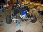
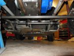
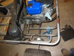
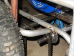
So I guess I got really lucky, and as I started considering the best way to cut the motor mount off, I turned the motor around just for the hell of it. Guess what...it fits even better backwards!!

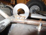
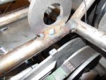
SO I got the motor flipped, and heres some pics of my jackshaft assembly underneath. I am getting really close to finishing up the drivetrain now!!:thumbsup:
 

Attachments

  • DSCN0352.jpg
    DSCN0352.jpg
    105.3 KB · Views: 38
  • DSCN0353.jpg
    DSCN0353.jpg
    112.6 KB · Views: 40
  • DSCN0354.jpg
    DSCN0354.jpg
    95.6 KB · Views: 40
  • DSCN0355.jpg
    DSCN0355.jpg
    83.7 KB · Views: 42
  • DSCN0357.jpg
    DSCN0357.jpg
    99.1 KB · Views: 36

Herky

New member
Messages
63
Reaction score
0
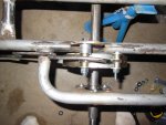
I had a little difficulty with the jackshaft washer mounts...they were twice as thick as my tubing, so I cranked up my Hobart 190 to 60 on the feed and 5 on the amperage to cut into the washers, but when I got near the tubing, I could feel it almost going through.

I think the welds are strong enough, but I'm not satisfied with the technique of welding dissimilar thickness metals. any ideas?
 

Attachments

  • DSCN0350.jpg
    DSCN0350.jpg
    105.3 KB · Views: 15
  • DSCN0349.jpg
    DSCN0349.jpg
    87 KB · Views: 15
  • DSCN0347.jpg
    DSCN0347.jpg
    106.3 KB · Views: 16

OzFab

Well-known member
Messages
15,615
Reaction score
67
Location
Warwick Qld, Australia
So I guess I got really lucky, I turned the motor around just for the hell of it. Guess what...it fits even better backwards!!

Sometimes, for no reason at all, we seem to land on our feet :thumbsup:

I had a little difficulty with the jackshaft washer mounts...they were twice as thick as my tubing, so I cranked up my Hobart 190 to 60 on the feed and 5 on the amperage to cut into the washers, but when I got near the tubing, I could feel it almost going through.

I think the welds are strong enough, but I'm not satisfied with the technique of welding dissimilar thickness metals. any ideas?

The tacks* in pic 1 look ok but the ones in pics 2 & 3 look a bit dodgy...

*Anything less than 1" is considered a tack...

The easiest way to weld dissimilar sized materials is to concentrate the heat to the thicker material (angle the gun so it points more to the thicker material). Also, when you weld, you use a zig zag or circular motion, correct? When doing this, spend less time on the thin material & more time on the thick stuff.
 

mckutzy

Well-known member
Messages
8,353
Reaction score
108
Location
bc, canada
I'd cut off those washers, grind off all the welds. Re weld them back on. It looks like when you have the gun in hand, the nozzle isn't held firmly In a good position, thus it is jumping around and making a few weld deposits and then movining to the next.
So on your next time, firmly plant yourself in the position that you can cover the whole weld area with the gun. Let'er rip and hold the nozzle near the weld area, with a slight C shape movements. Don't move the rest of your body, just your wrists. Check the throw with the gun befor you start.
 

Herky

New member
Messages
63
Reaction score
0
good advice-
thanks mckutzy and Fabroman.

I started with tacks on either side of the washers, then started alternating sides, so the heat wouldn't pull them out of position. ended up with what you see in the pics.
 

mckutzy

Well-known member
Messages
8,353
Reaction score
108
Location
bc, canada
If it(the washer) is pulling to one side, set up a an angle iron where it can clamp to it and to the frame. That will help set the position so it wont move but allow it to have less heat absorption (Both frame and the part welded).

Hows alignment with these things, to me it seems like this is a nightmare to have good steup where everything is straight?
 

Herky

New member
Messages
63
Reaction score
0
well, I spent a lot of time "eyeballing" it...tacking and re-tacking. I tried to square everything up against the axle itself. I think it's pretty good (I did use a tape measure lol)

One major problem I found is that the axle is fixed, and this jackshaft setup is now fixed as well...don't know how to adjust final chain...just remove a link? wont stretch THAT much...

I can adjust the (secondary?) chain from the TAV to the jackshaft via sliding the motor in the slots.
 

Herky

New member
Messages
63
Reaction score
0
One more question...any input on placing the drive sprocket on the far right side, and having the drum brake on the far LEFT side?

I suppose i may get more twisting moment out of the axle when the two forces oppose across the length of the axle, vs if the sprocket and brake drum were only a few inches apart.
 

OzFab

Well-known member
Messages
15,615
Reaction score
67
Location
Warwick Qld, Australia
well, I spent a lot of time "eyeballing" it...tacking and re-tacking. I tried to square everything up against the axle itself. I think it's pretty good (I did use a tape measure lol)

Well, here's a (better late than never) tip; find a length of tube, pipe, whatever with the same OD as the washers ID. Fit snugly, it will hold the washers square to the pipe & parallel to each other. Then it;s a simple matter of tacking one end of one, checking it's square then tacking the other.

One major problem I found is that the axle is fixed, and this jackshaft setup is now fixed as well...don't know how to adjust final chain...just remove a link? wont stretch THAT much...

Chain tensioner?

One more question...any input on placing the drive sprocket on the far right side, and having the drum brake on the far LEFT side?

I suppose i may get more twisting moment out of the axle when the two forces oppose across the length of the axle, vs if the sprocket and brake drum were only a few inches apart.

You may get a little that may affect the axle in a few years but, not enough to worry about.

Some time ago, I bought a racing kart. If you look, you'll see that the sprocket is on the far right of the 1" solid axle & the brake disc is on the far left...
 

Herky

New member
Messages
63
Reaction score
0
So, still chugging away...waiting for a #35 sprocket for my jackshaft (sent me two #41s instead of one of each). The split main sprocket arrived a few days ago...looks really cool!
Unfortunately my sprocket hub is just a few thousandths too small to fit the 1" axle. I asked my uncle to send me a reamer from Montana to open it up a little.

In the meantime, I was looking at my 6" drum brake setup...I need to rig up a hard mount to the frame for the fixed end of the band. Should be fairly easy, I have some strap steel I can cut up.
 

dnuccio

New member
Messages
55
Reaction score
0
Location
AZ
you should be using pillow block bearings to hold your jackshaft, not some washers. the holes in the washers are going to get worn out of shape really fast, and the whole jackshaft is gonna wobble.

unless theres something im not understanding here.
 

Herky

New member
Messages
63
Reaction score
0

Herky

New member
Messages
63
Reaction score
0
Working on my brake setup today a little...it was 103 this afternoon so I took a break, and never got back to it tonight like I wanted.

I think I have my strategy figured out though. Just some re-bending of the 1/4" brake rod, a little welding to re-mount the fixed portion of the band, and...oah lah! (easier said than spelled lol!)

Only problem I can see with the setup (sorry no pic yet) is that I don't know how to adjust it. I'm a little afraid of setting it up with no ability to adjust...but I think the original Manco brake had no adjustment either.

It has a spring halfway down the brake rod to connect the two halves...I believe that is there to give the brakes a little tension and "feel" instead of just having 1/8" of brake travel and, "SCREEE"! lockup rear axle!!! Nicely done Manco! Almost makes up for having no way to take slack out of system when the band wears down ha ha!
 

Herky

New member
Messages
63
Reaction score
0
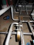
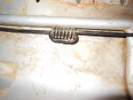
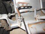
got hardware tonight and was able to finish my brake setup. I think it's going to be a pretty reliable and straightforward setup.

I'm a little concearned about the articulating side of the band 'walking' over left or right off center from the drum. I was thinking about adding a guide on the top so it didn't creep to one side or the other.
:cheers2:
 

Attachments

  • DSCN0407.jpg
    DSCN0407.jpg
    91.3 KB · Views: 28
  • DSCN0409.jpg
    DSCN0409.jpg
    86.7 KB · Views: 27
  • DSCN0412.jpg
    DSCN0412.jpg
    86.4 KB · Views: 28
  • DSCN0413.jpg
    DSCN0413.jpg
    83.2 KB · Views: 21
  • DSCN0414.jpg
    DSCN0414.jpg
    101.1 KB · Views: 24
Status
Not open for further replies.
Top