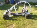
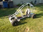
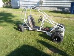
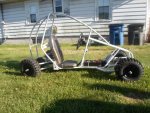
Lunar Rover (prototype)

Functional Artist

Well-known member
Messages
5,628
Reaction score
3,264
Location
Toledo, Ohio
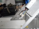
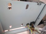
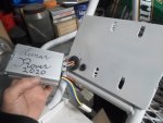
Before drillin' the holes for mountin' & wirin', I double checked/made sure that the speed controller would not intrude into the "battery box" area :cheers2:
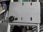
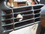
…& also, did a bit of scrollin' on the back of the SC ;)

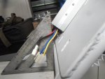
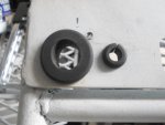
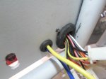
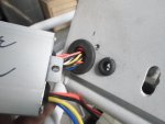
Added some rubber grommets
…then, simply "poked" the plugs/wires thru
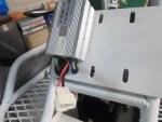
…hooked 'er on the top
…& finally, added a screw to secure it to the kart :thumbsup:

It's a good-n-solid mounting
…& the "plate" that it's mounted to, will also act as a "heat sink" to help dissipate any excess heat :2guns:
 

Attachments

  • SAM_4767.JPG
    SAM_4767.JPG
    312.3 KB · Views: 2
  • SAM_4768.JPG
    SAM_4768.JPG
    315 KB · Views: 3
  • SAM_4841.JPG
    SAM_4841.JPG
    309.7 KB · Views: 1
  • SAM_4842.JPG
    SAM_4842.JPG
    312.6 KB · Views: 1
  • SAM_4839.JPG
    SAM_4839.JPG
    315.2 KB · Views: 1
  • SAM_4852.JPG
    SAM_4852.JPG
    313.8 KB · Views: 1
  • SAM_4850.JPG
    SAM_4850.JPG
    308 KB · Views: 1
  • SAM_4848.JPG
    SAM_4848.JPG
    311.2 KB · Views: 1
  • SAM_4845.JPG
    SAM_4845.JPG
    306.9 KB · Views: 1
  • SAM_4844.JPG
    SAM_4844.JPG
    309.8 KB · Views: 1
Functional Artist

Well-known member
Messages
5,628
Reaction score
3,264
Location
Toledo, Ohio
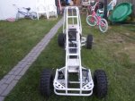
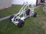
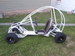
I got the Rover out :thumbsup:
...finally, put 'er together :cheers2:
...& took 'er for a test ride :2guns:

It's just a front wheel drive kart, for now :rolleyes:

* I must say, driving an articulating kart is gonna take some "gettin' used to" :popcorn:

https://www.youtube.com/watch?v=aFvmfaUmYDU
 

Attachments

  • SAM_5374.JPG
    SAM_5374.JPG
    311.4 KB · Views: 3
  • SAM_5371.JPG
    SAM_5371.JPG
    308.1 KB · Views: 2
  • SAM_5369.JPG
    SAM_5369.JPG
    312.7 KB · Views: 4
  • SAM_5377.JPG
    SAM_5377.JPG
    304.9 KB · Views: 3
  • SAM_5376.JPG
    SAM_5376.JPG
    310.6 KB · Views: 3
  • SAM_5379.JPG
    SAM_5379.JPG
    303.6 KB · Views: 4
  • SAM_5380.JPG
    SAM_5380.JPG
    305.4 KB · Views: 3

SquidBonez

Active member
Messages
512
Reaction score
132
Location
New Jersey, USA
That's some very impressive metal work! I'm sure even at 2000W that kart is gonna have a lot of low end torque being electric and all. Very interesting to see a 4WD kart. Keep us posted.
 

BigWes

Member
Messages
829
Reaction score
32
Location
Alabama
After watching the video I have to wonder if the FA carries a pocket full of fuses with him where ever he goes or if there is like a spares kit on board his karts!

The last time I bought some fuses like that they got expensive real fast!
 

Functional Artist

Well-known member
Messages
5,628
Reaction score
3,264
Location
Toledo, Ohio
That's some very impressive metal work! I'm sure even at 2000W that kart is gonna have a lot of low end torque being electric and all. Very interesting to see a 4WD kart. Keep us posted.

Thanks! :thumbsup:
...more to come :cool:

---------- Post added at 10:58 PM ---------- Previous post was at 10:54 PM ----------

looks good! but what about a seat belt. It has a roll cage.
https://www.youtube.com/watch?v=Tvt1-RjWws0

Thanks! :thumbsup:

Nope, no seat belts :cheers2:
...it's specifically designed for easy entry/exit
...& for the driver to be "thrown clear" in the event of a roll over/crash :huh:
 

Functional Artist

Well-known member
Messages
5,628
Reaction score
3,264
Location
Toledo, Ohio
After watching the video I have to wonder if the FA carries a pocket full of fuses with him where ever he goes or if there is like a spares kit on board his karts!

The last time I bought some fuses like that they got expensive real fast!

Um, doesn't everybody carry "spare fuses"? :rolleyes:

There's "tricks" to almost everything :thumbsup:

It's Top Secret
...so, don't tell no one ;)

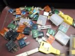
When ever I go to an automotive "junk yard", I leave with a pocket full of fuses :cheers2:
(with permission, of course) :cool:

Most cars have ~10 misc amperage fuses in their fuse box
...some even have "new" fuses/kits in the glove box :2guns:

I can almost "taste the rainbow" :lolgoku:
 

Attachments

  • SAM_5393.JPG
    SAM_5393.JPG
    322.9 KB · Views: 1
  • SAM_5392.JPG
    SAM_5392.JPG
    316.3 KB · Views: 1
  • SAM_5391.JPG
    SAM_5391.JPG
    320.2 KB · Views: 1
  • SAM_5390.JPG
    SAM_5390.JPG
    315.5 KB · Views: 1

Functional Artist

Well-known member
Messages
5,628
Reaction score
3,264
Location
Toledo, Ohio
Gettin' back to the Rover :thumbsup:

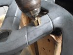
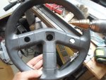
We need (2) switches :cheers2:
...(1) for the On/Off switch
...& (1) for the reverse switch :2guns:

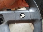
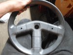
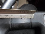
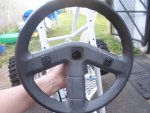
I'm thinkin', Ima gonna mount 'em right on the steering wheel
 

Attachments

  • SAM_5402.JPG
    SAM_5402.JPG
    318.6 KB · Views: 1
  • SAM_5401.JPG
    SAM_5401.JPG
    313.6 KB · Views: 1
  • SAM_5397.JPG
    SAM_5397.JPG
    314.1 KB · Views: 1
  • SAM_5395.JPG
    SAM_5395.JPG
    314.4 KB · Views: 1
  • SAM_5394.JPG
    SAM_5394.JPG
    317.7 KB · Views: 1
  • SAM_5403.JPG
    SAM_5403.JPG
    317.1 KB · Views: 1
  • SAM_5404.JPG
    SAM_5404.JPG
    315.8 KB · Views: 1
  • SAM_5405.JPG
    SAM_5405.JPG
    313.3 KB · Views: 1
Functional Artist

Well-known member
Messages
5,628
Reaction score
3,264
Location
Toledo, Ohio
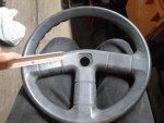
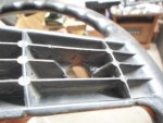
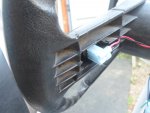
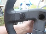
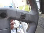
I put the On/Off switch on the right side (quickly accessible kinda like a "kill switch") :thumbsup:
...& the reverse switch on the left side

Also, to help differentiate the (2) switches, I mounted the On/Off switch oriented "up & down"
...& the reverse switch oriented "side to side" :2guns:

I used some "flag style" spade terminals
...to help keep the wires up nice-n-close to the steering wheel :cheers2:
 

Attachments

  • SAM_5458.JPG
    SAM_5458.JPG
    313.3 KB · Views: 0
  • SAM_5455.JPG
    SAM_5455.JPG
    311 KB · Views: 0
  • SAM_5456.JPG
    SAM_5456.JPG
    314.8 KB · Views: 0
  • SAM_5454.JPG
    SAM_5454.JPG
    312.8 KB · Views: 0

Functional Artist

Well-known member
Messages
5,628
Reaction score
3,264
Location
Toledo, Ohio
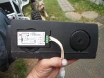
Next let's get the "power meter" connected & mounted :thumbsup:

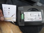
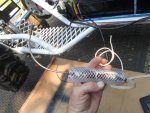
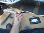
I came across a (4) wire "strip" from an old electric blanket :cheers2:
...it has (4) separate (~16g.) wires that are kinda "glued" together

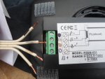
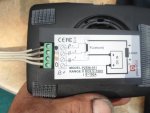
The first thing I did was to "color code" 'em (the wires & the meter too) ;)

Black = P- (goes to the small "signal" terminal, on the "load" side of the shunt)
Silver = B-2 (goes to the small "signal" terminal, on the battery side of the shunt)
Gold = B- (goes to the big "main" terminal, on the battery side of the shunt)
White = B+ (goes to the positive (+) terminal of the battery, itself)

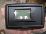
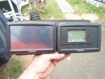
Then, I mounted the "power meter" (PZEM-051) to a plastic dash plate along with
...& right next to the "proximity meter" (Tom Tom GPS) :cornut:

These will tell us whats goin' on "in" the kart
...& also what's goin' on "around" the kart too :2guns:
 

Attachments

  • SAM_5492.JPG
    SAM_5492.JPG
    307.9 KB · Views: 0
  • SAM_5491.JPG
    SAM_5491.JPG
    310.4 KB · Views: 0
  • SAM_5468.JPG
    SAM_5468.JPG
    316 KB · Views: 0
  • SAM_5466.JPG
    SAM_5466.JPG
    314.1 KB · Views: 0
  • SAM_3174.JPG
    SAM_3174.JPG
    312.7 KB · Views: 0
  • SAM_5493.JPG
    SAM_5493.JPG
    316.2 KB · Views: 1
  • SAM_5495.JPG
    SAM_5495.JPG
    307.2 KB · Views: 0
  • SAM_5494.JPG
    SAM_5494.JPG
    312.7 KB · Views: 0

Functional Artist

Well-known member
Messages
5,628
Reaction score
3,264
Location
Toledo, Ohio
Major Cluster Phuck

Um...Houston...I think, we have a problem :huh:

I made up a harness to connect/power the rear motor
...but, when I hooked 'er up, some things didn't seem to be workin' right :censored:

So, I gave 'er a look over
...& everything seemed to be connected properly :thumbsup:

Then, I took 'er for a quick "test" ride
...& things got even weirder :ack2:

Like when, I "flipped" the On/Off switch to "on", it seemed like I could only hear (1) SC "click" on
...& then, when I tried to accelerate, the rear wheels would "break loose" & spin violently :smiley_omg:
So, I brought 'er home & did some investigating.
...that's when I noticed, that the front SC stopped workin' :mad:

Thought it thru, several times
...& everything still seemed correct :cheers2:

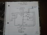
So, I drew up a wiring diagram
...& that's when I noticed the "fatal flaw"(can ya find it?) :oops:

Then, while disconnecting the "bad" SC
...I noticed that I had the On/Off switch "power lock" wires, "cris-crossed" too (WTF?)

* On a single SC/motor system the (2) "power lock" wires usually just "close" a circuit
...but, on a "dual" SC system IDK what would happen TBH

Then, to make things worse (can it get any worse?)
...I also, noticed that I criss-crossed the throttle wires too

The black neg (-) wires were connected properly
...but, I had the 5V power (+) from the front SC connected to the signal wire going to the rear SC

** That help to explain why the rear wheels were "breakin' loose"
...I would say, that when the pedal was pressed, a direct 5V was being sent to (1) of the SC's

*** I probably should have kept this to myself
...& not even post this or admit to these many F-up's
...but, these things really happen

So, the moral of this story is that "ya gotta, stay on your toes"
...even if ya "think" ya know what your doin' :2guns:
 

Attachments

  • SAM_5452.JPG
    SAM_5452.JPG
    306.4 KB · Views: 6

Brianator

Gettin' er done!
Messages
860
Reaction score
18
Location
Barrie, Ontario, Canada
You didn't get this far (overall) without making mistakes and learning from them! At least you're big enough to admit it and I don't think any less of ya for it! You're doing a great job keep er up! :cheers2:

It's not overly detailed albiet a good "road map", but according to your diagram I wouldn't be surprised to find out the rear wheels were peeling out in reverse as the wires are switched around as compared to the front motor AND the rear reverse switch isn't connected as of yet. Everything else appears to be on the up and up though!
 

Functional Artist

Well-known member
Messages
5,628
Reaction score
3,264
Location
Toledo, Ohio
You didn't get this far (overall) without making mistakes and learning from them! At least you're big enough to admit it and I don't think any less of ya for it! You're doing a great job keep er up! :cheers2:

It's not overly detailed albiet a good "road map", but according to your diagram I wouldn't be surprised to find out the rear wheels were peeling out in reverse as the wires are switched around as compared to the front motor AND the rear reverse switch isn't connected as of yet. Everything else appears to be on the up and up though!

Thanks! :thumbsup:

It seems like I learn something new everyday :cheers2:
...most times it's "what NOT to do" :lolgoku:

Yup, the reverse circuit is the culprit, in the diagram :ack2:

Actually everything should be/work fine (that's why everything looked proper, at first)

It's only "if" or when the reverse switch was engaged, that the problems would "appear" :huh:

Because the reverse switch is only "switching" the front motor, into reverse
...but, not the rear motor

So, when the throttle was applied, the front motor would wanna go backwards
...& the rear motor would still want to go forward :mad2:

* Remember the throttle "signals" of the (2) SC's are connected together
...but, if only (1) SC gets "switched" into reverse, the other motor doesn't know "let's go backwards now"
...& just goes...forward :2guns:

** I didn't bother to wire/connect the reverse function on the rear SC
...because, I didn't figure we needed dual "power" or (4WD) while goin' backwards :oops:
 

Brianator

Gettin' er done!
Messages
860
Reaction score
18
Location
Barrie, Ontario, Canada
You'll sure wish you had reverse 4wd if you get stuck in some lunar crud"! Why not go with selectable 2/4wd for reverse? Im sure a (6 pin) DPDT switch and a standard 5 pin, 12 volt relay could make it happen. I just need to know if the reverse circuit is NO or NC (I'd assume NO) and a little time to draw it out after work. I can map it out in my head but until I see it on paper.... well, you know! Lol
 

Functional Artist

Well-known member
Messages
5,628
Reaction score
3,264
Location
Toledo, Ohio
You'll sure wish you had reverse 4wd if you get stuck in some lunar crud"! Why not go with selectable 2/4wd for reverse? Im sure a (6 pin) DPDT switch and a standard 5 pin, 12 volt relay could make it happen. I just need to know if the reverse circuit is NO or NC (I'd assume NO) and a little time to draw it out after work. I can map it out in my head but until I see it on paper.... well, you know! Lol

On these SC's the On/Off function & the reverse function are both (NO) normally open circuits :thumbsup:

When the switch is "flipped" it closes the circuit
...& activates the function :cheers2:

The "proper" way (which I should have done in the beginning) would have been to connect both reverse connections, to the "reverse" switch :2guns:
(just like both of the On/Off connections are wired to the "On/Off" switch)

* This configuration will provide Full Time 4WD
...& a more powerful reverse action too

Double Bonus :cool:
 

Brianator

Gettin' er done!
Messages
860
Reaction score
18
Location
Barrie, Ontario, Canada
No reverse donuts for you! Lol. I realized I overcomplicated it anyhow, with a NC momentary contact pushbutton you could probably achieve the same goal by interrupting the signal to the SC for the rear motor.
 

Functional Artist

Well-known member
Messages
5,628
Reaction score
3,264
Location
Toledo, Ohio
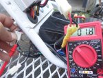
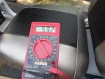
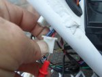
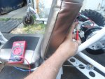
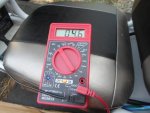
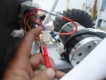
I took some voltage readings
...from both SC's (#1 non functional & #2 functional)
...just for documentation purposes :cheers2:

The first line of data is when the SC's are "switched" off
...& the second line is with the SC's "switched" on

It looks like the only inconsistency is "on" the red "power in" wire in the throttle circuit
...on SC#1 (damaged) it only shows 1.8V
...but, on SC #2 (not damaged) it shows 4.6V
 

Attachments

  • SAM_5410.JPG
    SAM_5410.JPG
    317.2 KB · Views: 1
  • SAM_5413.JPG
    SAM_5413.JPG
    302.6 KB · Views: 1
  • SAM_5411.JPG
    SAM_5411.JPG
    304 KB · Views: 1
  • SAM_5414.JPG
    SAM_5414.JPG
    313.9 KB · Views: 0
  • SAM_5415.JPG
    SAM_5415.JPG
    307.1 KB · Views: 0
  • SAM_5416.JPG
    SAM_5416.JPG
    315.4 KB · Views: 0
  • SAM_5418.JPG
    SAM_5418.JPG
    308.7 KB · Views: 2
Top