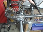
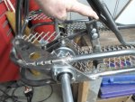
Lunar Rover (prototype)

Functional Artist

Well-known member
Messages
5,628
Reaction score
3,264
Location
Toledo, Ohio
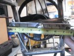
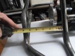
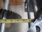
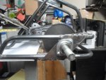
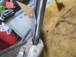
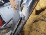
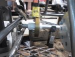
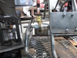
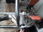
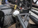
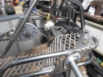
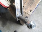
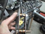
The connections, on the front steering cross-bar, are currently ~3 1/2" from the center
...but, I can easily add holes & adjust the connections to the 2 1/2" or 1 1/2" marks


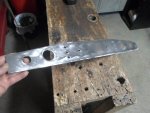
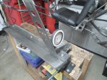
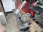
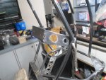
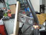
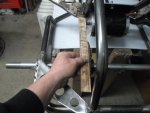
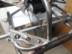
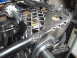
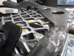
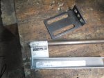
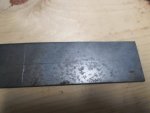
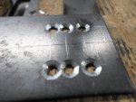
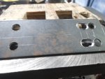
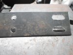
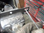
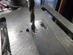
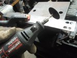
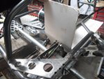
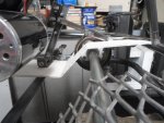
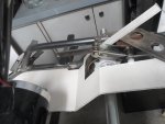
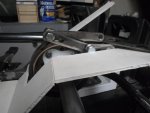
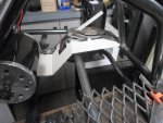
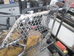
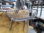
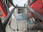
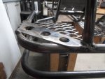
Moving on, I cut a piece of steel for an upper seatback mounting bracket :thumbsup:
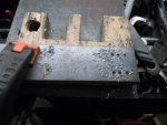
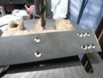
...added seat mounting holes
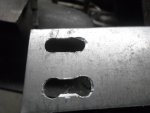
...bending relief holes
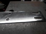
...& also, a couple of bigger holes to look kool & reduce weight a bit :cheers2:
...then, bent 'er into shape :2guns:
 

Attachments

  • SAM_2503.JPG
    SAM_2503.JPG
    314.7 KB · Views: 1
  • SAM_2504.JPG
    SAM_2504.JPG
    313.4 KB · Views: 1
  • SAM_2507.JPG
    SAM_2507.JPG
    315.4 KB · Views: 2
  • SAM_2512.JPG
    SAM_2512.JPG
    315.8 KB · Views: 2
  • SAM_2515.JPG
    SAM_2515.JPG
    314.5 KB · Views: 2

Functional Artist

Well-known member
Messages
5,628
Reaction score
3,264
Location
Toledo, Ohio
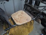
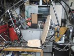
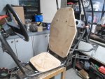
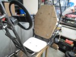
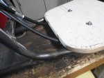
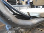
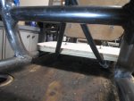
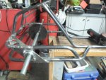
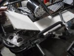
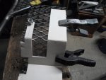
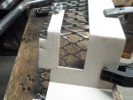
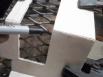
Next, I cut a custom base/foundation for our seat back & bottom, outta some 1/2" plywood :thumbsup:

Shaped 'em to kinda match the frame :2guns:

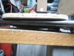
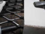
I made sure the seat base, mounting bar, sat nice-n-flush
…& the steering cables clear nicely as well :cheers2:
 

Attachments

  • SAM_2548.JPG
    SAM_2548.JPG
    320.6 KB · Views: 1
  • SAM_2543.JPG
    SAM_2543.JPG
    315 KB · Views: 1
  • SAM_2520.JPG
    SAM_2520.JPG
    321.4 KB · Views: 1
  • SAM_2519.JPG
    SAM_2519.JPG
    316.9 KB · Views: 1
  • SAM_2518.JPG
    SAM_2518.JPG
    315.2 KB · Views: 1
  • SAM_2551.JPG
    SAM_2551.JPG
    317.3 KB · Views: 1
  • SAM_2553.JPG
    SAM_2553.JPG
    319.1 KB · Views: 1
  • SAM_2559.JPG
    SAM_2559.JPG
    315.9 KB · Views: 1
  • SAM_2560.JPG
    SAM_2560.JPG
    313.9 KB · Views: 1
  • SAM_2561.JPG
    SAM_2561.JPG
    317.4 KB · Views: 1

Functional Artist

Well-known member
Messages
5,628
Reaction score
3,264
Location
Toledo, Ohio
Gotta round up some upholstery
...to give 'er a protective cover & some paddin' :thumbsup:

Until then...

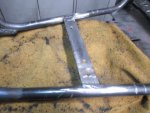
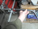
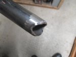
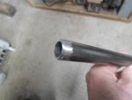
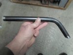
I cut, bent up & installed a couple of bars
...these will act as protective barriers between the astro-drivers feet & the front wheels :cheers2:
...…& also, to "tie together" & strengthen the (2) tiers (upper & lower) of the front end :2guns:
 

Attachments

  • SAM_2531.JPG
    SAM_2531.JPG
    315.3 KB · Views: 1
  • SAM_2529.JPG
    SAM_2529.JPG
    314.6 KB · Views: 1
  • SAM_2526.JPG
    SAM_2526.JPG
    301.9 KB · Views: 1
  • SAM_2525.JPG
    SAM_2525.JPG
    296 KB · Views: 1
  • SAM_2524.JPG
    SAM_2524.JPG
    318.3 KB · Views: 1
  • SAM_2533.JPG
    SAM_2533.JPG
    313.3 KB · Views: 1
  • SAM_2572.JPG
    SAM_2572.JPG
    310.6 KB · Views: 1
  • SAM_2579.JPG
    SAM_2579.JPG
    315.7 KB · Views: 1
  • SAM_2591.JPG
    SAM_2591.JPG
    312.3 KB · Views: 1

Functional Artist

Well-known member
Messages
5,628
Reaction score
3,264
Location
Toledo, Ohio
I'ma thinkin' we'll work on the front "drive unit" next
...set up, test etc.

She'll basically be a front wheel drive kart
...but, just for a minute :thumbsup:

I thought about settin' the front up with "dual compatibility"
...so, either a live axle or a diff could be installed.
...but, ran into some issues

The sprocket on a live axle can be adjusted almost infinitely, not so much on a diff :huh:

I have a peerless differential, out of a riding mower, that I used for measurement purposes.
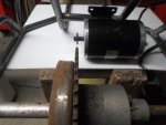
...but, with the diff centered, in the frame & the sprockets aligned, the back of the motor would intrude into the operators foot area a bit. (~1 1/2") :ack2:

So, live axle "it is" :cheers2:
...maybe we'll put a diff on the "tail" to aid steering/maneuverability :2guns:
 

Attachments

  • SAM_2594.JPG
    SAM_2594.JPG
    315.6 KB · Views: 0
  • SAM_2590.JPG
    SAM_2590.JPG
    306.4 KB · Views: 0
  • SAM_2589.JPG
    SAM_2589.JPG
    314.6 KB · Views: 0
  • SAM_2583.JPG
    SAM_2583.JPG
    312.7 KB · Views: 0
  • SAM_2581.JPG
    SAM_2581.JPG
    314.3 KB · Views: 0

Functional Artist

Well-known member
Messages
5,628
Reaction score
3,264
Location
Toledo, Ohio
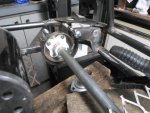
Front Motor Mount

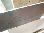
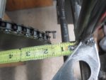
I cut a piece of 10g. steel to use as a motor mount (it's a bit thicker than 1/8" steel which is ~12g.)
…added (4) adjustment slots
…& then, clamped 'er to the upright bars, right behind the axle/sprocket :thumbsup:

* Used a straight edge to align the sprockets

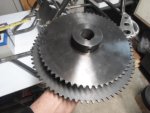
First, I tried a 60T sprocket
…there was ~2" of clearance from the front bumper/bars

Then, tried a 72T sprocket
…& there was ~1 1/4" of clearance

** The 60T sprocket will make 'er faster :2guns:
...but, the 72T sprocket will give 'er more torque :cheers2:

Ima gonna go with more torque, for now (better for climbin' outta craters-n-such) :cool:
...but, can always switch 'em later (like for racin' with/against alien rovers/karts) :wai:
 

Attachments

  • SAM_2682.JPG
    SAM_2682.JPG
    302.7 KB · Views: 0
  • SAM_2656.JPG
    SAM_2656.JPG
    308.6 KB · Views: 1
  • SAM_2657.JPG
    SAM_2657.JPG
    316.1 KB · Views: 0
  • SAM_2664.JPG
    SAM_2664.JPG
    311.3 KB · Views: 0
  • SAM_2670.JPG
    SAM_2670.JPG
    309.1 KB · Views: 0
  • SAM_2677.JPG
    SAM_2677.JPG
    312.3 KB · Views: 2
  • SAM_2680.JPG
    SAM_2680.JPG
    312.8 KB · Views: 0
  • SAM_2673.JPG
    SAM_2673.JPG
    316.9 KB · Views: 0
  • SAM_2672.JPG
    SAM_2672.JPG
    300.3 KB · Views: 0
  • SAM_2668.JPG
    SAM_2668.JPG
    312.3 KB · Views: 0

Functional Artist

Well-known member
Messages
5,628
Reaction score
3,264
Location
Toledo, Ohio
Floor Boards

I tac welded the motor mount plate in place
…& then re-installed/assembled the axle, sprocket, motor & chain
(just to be sure it's where it needs to be before weldin' 'er down good-n- permanent)

Yup, looks good :thumbsup:

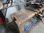
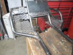
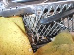
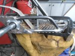
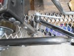
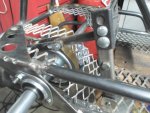
Next, I moved on to the floor boards
...which I'm also gonna try to incorporate the axle/chain guard into as well :cheers2:

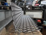
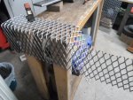
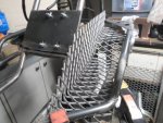
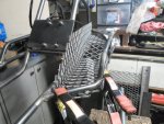
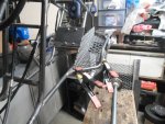
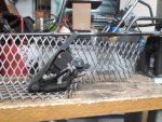
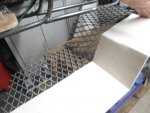
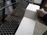
So, I measured, marked, cut & bent a piece of expanded steel
...but, when I tried a "test fit", it just seems like too much (kinda overbuilt) :huh:

Now, I'm workin' on something a bit smaller
...more to come :2guns:
 

Attachments

  • SAM_2695.JPG
    SAM_2695.JPG
    312.6 KB · Views: 1
  • SAM_2693.JPG
    SAM_2693.JPG
    316.2 KB · Views: 1
  • SAM_2696.JPG
    SAM_2696.JPG
    316.9 KB · Views: 1
  • SAM_2737.JPG
    SAM_2737.JPG
    313.8 KB · Views: 1
  • SAM_2739.JPG
    SAM_2739.JPG
    316.7 KB · Views: 1
  • SAM_2747.JPG
    SAM_2747.JPG
    317.6 KB · Views: 2
  • SAM_2745.JPG
    SAM_2745.JPG
    313.7 KB · Views: 1
  • SAM_2746.JPG
    SAM_2746.JPG
    315.7 KB · Views: 1
  • SAM_2744.JPG
    SAM_2744.JPG
    322.6 KB · Views: 1
  • SAM_2743.JPG
    SAM_2743.JPG
    317.4 KB · Views: 1

Functional Artist

Well-known member
Messages
5,628
Reaction score
3,264
Location
Toledo, Ohio
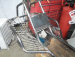
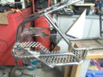
Floor boards 2.0

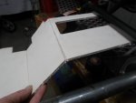
I came up with some smaller floorboards :thumbsup:
...but, the actual floor/foot space did not decrease

They go across/under the foot area
...then, rise's up @ ~45*
…then, level out
…& finally tucks up under the front bearing bracket stress plates :cheers2:

Gives a nice-n-clean look
...& also, isolates the rotating shaft from the foot/pedal area :2guns:
 

Attachments

  • SAM_2793.JPG
    SAM_2793.JPG
    316.9 KB · Views: 0
  • SAM_2794.JPG
    SAM_2794.JPG
    313.9 KB · Views: 0
  • SAM_2795.JPG
    SAM_2795.JPG
    321.2 KB · Views: 2
  • SAM_2798.JPG
    SAM_2798.JPG
    314.5 KB · Views: 0
  • SAM_2797.JPG
    SAM_2797.JPG
    322 KB · Views: 0

Functional Artist

Well-known member
Messages
5,628
Reaction score
3,264
Location
Toledo, Ohio
Before I can make/install the left floor board, we gotta work on the braking system :thumbsup:

First, we have to establish
...what type of brake system
...how it's gonna function
…& where & how it's gonna be mounted

Then, make a brake pedal
...& figure where it needs to be mounted :cheers2:


Well, it looks like it would be simplest to just mount a drum brake
...right in front of where the brake pedal, will be
…& have it actuated directly, by the pedal, via a short metal bar :2guns:

* It would put a whole new meaning to "Stompin' on the Brakes" :lolgoku:

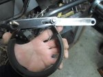
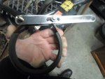
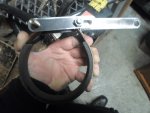
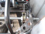
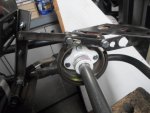
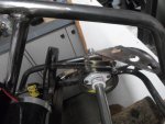
So, to mount the "pivot side" of the brake band to the frame, I used a 3/8" "long nut" on the frame side, of the brake drum
…& made up a bracket to support the "inner" side

Made sure everything was square, with the axle & then, tacked 'em on

Now, I am gonna make up a brake pedal
…& a "connecting rod"
…& then, do some testin' (to see if/how well it functions/works) :wai:
 

Attachments

  • SAM_2817.JPG
    SAM_2817.JPG
    316.3 KB · Views: 0
  • SAM_2816.JPG
    SAM_2816.JPG
    313 KB · Views: 1
  • SAM_2815.JPG
    SAM_2815.JPG
    313.8 KB · Views: 0
  • SAM_2812.JPG
    SAM_2812.JPG
    313 KB · Views: 1
  • SAM_2811.JPG
    SAM_2811.JPG
    314.6 KB · Views: 0

Functional Artist

Well-known member
Messages
5,628
Reaction score
3,264
Location
Toledo, Ohio
Brake Pedal

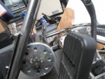
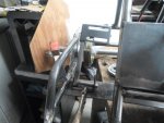
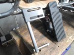
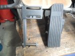
I rounded up some steel that seemed like it would make for a good pedal :thumbsup:
…& then, made up a simple U-bracket, for mounting it to the kart

Looks pretty good, paired with the throttle pedal :2guns:
 

Attachments

  • SAM_2851.JPG
    SAM_2851.JPG
    310.8 KB · Views: 0
  • SAM_2852.JPG
    SAM_2852.JPG
    310.9 KB · Views: 0
  • SAM_2853.JPG
    SAM_2853.JPG
    317.8 KB · Views: 0
  • SAM_2855.JPG
    SAM_2855.JPG
    315.4 KB · Views: 0
  • SAM_2857.JPG
    SAM_2857.JPG
    316.9 KB · Views: 0
  • SAM_2877.JPG
    SAM_2877.JPG
    311.8 KB · Views: 0
  • SAM_2873.JPG
    SAM_2873.JPG
    309.9 KB · Views: 1
  • SAM_2861.JPG
    SAM_2861.JPG
    312.8 KB · Views: 0
  • SAM_2859.JPG
    SAM_2859.JPG
    312.3 KB · Views: 0
  • SAM_2865.JPG
    SAM_2865.JPG
    315.2 KB · Views: 0

Functional Artist

Well-known member
Messages
5,628
Reaction score
3,264
Location
Toledo, Ohio
Brake Pedal Connecting Rod

I measured, marked, cut, & drilled a piece of 1/8" x 1" steel to use for the brake connecting rod
(it's pretty simple so, I forgot to take pics) :mad2:

But then, when I connected everything together & gave 'er a try
...the brake band kept floppin' around :huh:
…& also, droppin' down/out of alignment with the brake drum :ack2:

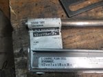
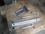
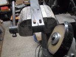
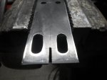
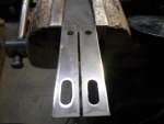
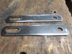
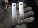
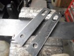
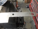
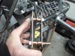
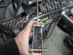
So, it looked like, maybe, a set of "sliding brake band retainers" may help :thumbsup:

These retainers don't need to be so Heavy Duty so, I'll just make 'em out of some 1/16" steel :cheers2:

I'll make them both simultaneously, right next to each other

Started off by measuring, marking, drilling, cutting, slotting & some filing too

Not bad so far :2guns:
 

Attachments

  • SAM_2878.JPG
    SAM_2878.JPG
    306.7 KB · Views: 0
  • SAM_2879.JPG
    SAM_2879.JPG
    306.7 KB · Views: 0
  • SAM_2882.JPG
    SAM_2882.JPG
    311 KB · Views: 0
  • SAM_2885.JPG
    SAM_2885.JPG
    312.6 KB · Views: 0
  • SAM_2889.JPG
    SAM_2889.JPG
    314.4 KB · Views: 0
  • SAM_2901.JPG
    SAM_2901.JPG
    314.4 KB · Views: 0
  • SAM_2900.JPG
    SAM_2900.JPG
    320 KB · Views: 0
  • SAM_2898.JPG
    SAM_2898.JPG
    312 KB · Views: 0
  • SAM_2892.JPG
    SAM_2892.JPG
    306.5 KB · Views: 0
  • SAM_2890.JPG
    SAM_2890.JPG
    310.6 KB · Views: 0

Functional Artist

Well-known member
Messages
5,628
Reaction score
3,264
Location
Toledo, Ohio
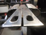
Next I had to cut 'em apart
…& then, clean 'em up :thumbsup:
 

Attachments

  • SAM_2904.JPG
    SAM_2904.JPG
    308.6 KB · Views: 0
  • SAM_2906.JPG
    SAM_2906.JPG
    314.6 KB · Views: 0
  • SAM_2907.JPG
    SAM_2907.JPG
    306.6 KB · Views: 0
  • SAM_2909.JPG
    SAM_2909.JPG
    314.7 KB · Views: 0
  • SAM_2910.JPG
    SAM_2910.JPG
    314.7 KB · Views: 0
  • SAM_2924.JPG
    SAM_2924.JPG
    315.1 KB · Views: 0
  • SAM_2917.JPG
    SAM_2917.JPG
    311.5 KB · Views: 0
  • SAM_2913.JPG
    SAM_2913.JPG
    319.2 KB · Views: 0
  • SAM_2912.JPG
    SAM_2912.JPG
    314.4 KB · Views: 0

Functional Artist

Well-known member
Messages
5,628
Reaction score
3,264
Location
Toledo, Ohio
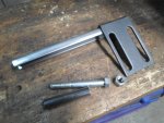
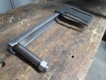
Brake Band Assembly with Sliding Retainers

Pics of the sliding retainers, mounted onto the brake band
...with the connecting rod :thumbsup:
 

Attachments

  • SAM_2948.JPG
    SAM_2948.JPG
    313.3 KB · Views: 0
  • SAM_2950.JPG
    SAM_2950.JPG
    312.9 KB · Views: 0
  • SAM_2951.JPG
    SAM_2951.JPG
    312.9 KB · Views: 0
  • SAM_2956.JPG
    SAM_2956.JPG
    320.1 KB · Views: 0
  • SAM_2955.JPG
    SAM_2955.JPG
    311.9 KB · Views: 0
  • SAM_2953.JPG
    SAM_2953.JPG
    310.9 KB · Views: 0

Functional Artist

Well-known member
Messages
5,628
Reaction score
3,264
Location
Toledo, Ohio
Brake Assembly Testing

I installed the brake band assy. around the axle
...& mounted onto the kart

Clamped the pedal down directly across from
...& "in line" with the throttle pedal

Connected 'em together with the connecting rod

Then, gave 'er a try :cheers2:

I tried (3) different connecting points on the pedal
...the middle one seemed to work the best :thumbsup:

Well, it works/functions
...but, still needs some adjustin' :huh:

So far, I'm likin' it :wai:
...short sweet & to the point :2guns:
 

Attachments

  • SAM_2936.JPG
    SAM_2936.JPG
    314.8 KB · Views: 1
  • SAM_2932.JPG
    SAM_2932.JPG
    316.2 KB · Views: 1
  • SAM_2930.JPG
    SAM_2930.JPG
    320.7 KB · Views: 1
  • SAM_2927.JPG
    SAM_2927.JPG
    317.7 KB · Views: 1
  • SAM_2926.JPG
    SAM_2926.JPG
    313.8 KB · Views: 1
  • SAM_2937.JPG
    SAM_2937.JPG
    315 KB · Views: 1

Functional Artist

Well-known member
Messages
5,628
Reaction score
3,264
Location
Toledo, Ohio
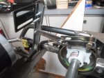
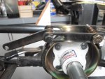
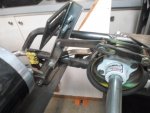
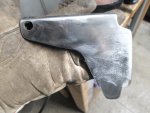
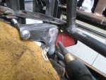
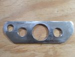
The first government issued brake band bracket (part # 100007062.79627-2.01) has been recalled :ack2:
...it just didn't meet specs for an "other world explorer" :huh:

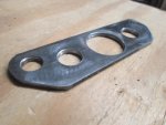
So, I've been workin' on installing the new "approved"
...& "improved" brake band bracket (part # 60279LR201.63B) on the Rover :thumbsup:

This "updated" version is a lot lighter
...& looks like it's more/better engineered too :2guns:
 

Attachments

  • SAM_2836.JPG
    SAM_2836.JPG
    309.5 KB · Views: 3
  • SAM_2840.JPG
    SAM_2840.JPG
    315.3 KB · Views: 5
  • SAM_2845.JPG
    SAM_2845.JPG
    315.5 KB · Views: 3
  • SAM_2960.JPG
    SAM_2960.JPG
    308.1 KB · Views: 3
  • SAM_2959.JPG
    SAM_2959.JPG
    315.6 KB · Views: 3
  • SAM_2963.JPG
    SAM_2963.JPG
    318.9 KB · Views: 3
  • SAM_2962.JPG
    SAM_2962.JPG
    307.7 KB · Views: 3
  • SAM_2961.JPG
    SAM_2961.JPG
    314.6 KB · Views: 3

Functional Artist

Well-known member
Messages
5,628
Reaction score
3,264
Location
Toledo, Ohio
Left floor board

The left floorboard has to work with/around the brake assembly, which makes it a bit more complicated

So, I made a template out of a piece of cardboard first, to help work out the fine 'er details :thumbsup:

Then, re-assembled the pedal assembly, to make sure everything "clears" & still functions properly :wai:

Looks good to me :2guns:
 

Attachments

  • SAM_3002.JPG
    SAM_3002.JPG
    307.1 KB · Views: 1
  • SAM_3004.JPG
    SAM_3004.JPG
    315.6 KB · Views: 1
  • SAM_3005.JPG
    SAM_3005.JPG
    319.7 KB · Views: 1
  • SAM_3007.JPG
    SAM_3007.JPG
    316.5 KB · Views: 1
  • SAM_3009.JPG
    SAM_3009.JPG
    298.7 KB · Views: 1
  • SAM_3020.JPG
    SAM_3020.JPG
    313.7 KB · Views: 1
  • SAM_3013.JPG
    SAM_3013.JPG
    307.8 KB · Views: 1
  • SAM_3012.JPG
    SAM_3012.JPG
    312.1 KB · Views: 1
  • SAM_3011.JPG
    SAM_3011.JPG
    314.9 KB · Views: 1

Functional Artist

Well-known member
Messages
5,628
Reaction score
3,264
Location
Toledo, Ohio
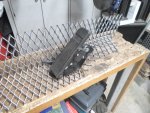
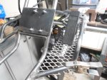
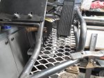
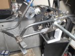
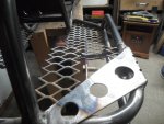
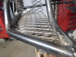
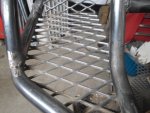
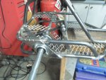
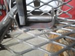
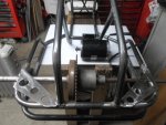
Making the floorboard, out of expanded steel, was pretty simple using the template :thumbsup:

Cut 'er out, lined 'er up, clamped 'er down & welded 'er on :cheers2:

Pretty & sturdy :2guns:
 

Attachments

  • SAM_3023.JPG
    SAM_3023.JPG
    310.9 KB · Views: 1
  • SAM_3024.JPG
    SAM_3024.JPG
    310.9 KB · Views: 1
  • SAM_3025.JPG
    SAM_3025.JPG
    310.7 KB · Views: 1
  • SAM_3026.JPG
    SAM_3026.JPG
    310.1 KB · Views: 1
  • SAM_3029.JPG
    SAM_3029.JPG
    312.4 KB · Views: 2
  • SAM_3040.JPG
    SAM_3040.JPG
    315.9 KB · Views: 2
  • SAM_3037.JPG
    SAM_3037.JPG
    316 KB · Views: 2
  • SAM_3036.JPG
    SAM_3036.JPG
    315 KB · Views: 2
  • SAM_3033.JPG
    SAM_3033.JPG
    315.9 KB · Views: 3
  • SAM_3031.JPG
    SAM_3031.JPG
    315.5 KB · Views: 2
Functional Artist

Well-known member
Messages
5,628
Reaction score
3,264
Location
Toledo, Ohio
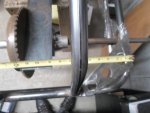
These floor boards will provide some protection :thumbsup:
…& won't pick up any "moon rocks" :wai:
Got a couple more pics :2guns:
 

Attachments

  • SAM_3039.JPG
    SAM_3039.JPG
    316.7 KB · Views: 3
  • SAM_3043.JPG
    SAM_3043.JPG
    317.2 KB · Views: 3
  • SAM_3042.JPG
    SAM_3042.JPG
    313.6 KB · Views: 2
  • SAM_3046.JPG
    SAM_3046.JPG
    315.5 KB · Views: 2
  • SAM_3045.JPG
    SAM_3045.JPG
    314.7 KB · Views: 2
Functional Artist

Well-known member
Messages
5,628
Reaction score
3,264
Location
Toledo, Ohio
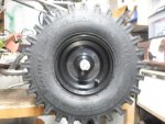
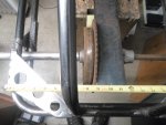
I think were gonna need something a bit "meaner" than turf savers, for climbin' outta craters-n-such :cool:

Like some really "grippy" tires :thumbsup:
...really really grippy :cheers2:
…even super grippy :wai:

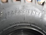
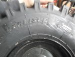
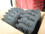
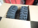
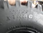
Yup, I think these Carlisle X-Trac (15 x 5.00 - 6) should work :bannana:
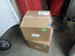
Picked 'em up from Surplus Center for ~$50.00 per pair :smiley_omg:
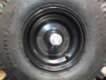
...can't beat (4) brand new rims & tires for ~$100.00 :sifone:

Um, I mean "Government Issued"
...yea, yea, their from the "Government" Surplus Center
 

Attachments

  • SAM_2974.JPG
    SAM_2974.JPG
    313.6 KB · Views: 1
  • SAM_2973.JPG
    SAM_2973.JPG
    315.2 KB · Views: 1
  • SAM_2971.JPG
    SAM_2971.JPG
    313.8 KB · Views: 1
  • SAM_2970.JPG
    SAM_2970.JPG
    310.3 KB · Views: 2
  • SAM_2967.JPG
    SAM_2967.JPG
    312.7 KB · Views: 1
  • SAM_2975.JPG
    SAM_2975.JPG
    312.9 KB · Views: 1

Functional Artist

Well-known member
Messages
5,628
Reaction score
3,264
Location
Toledo, Ohio
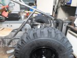
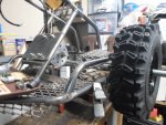
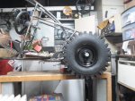
Here's how these X-Trac's look on the front of the kart :thumbsup:

Um...Corona wheels :ack2:
 

Attachments

  • SAM_3000.JPG
    SAM_3000.JPG
    313.4 KB · Views: 3
  • SAM_2995.JPG
    SAM_2995.JPG
    314.9 KB · Views: 3
  • SAM_2994.JPG
    SAM_2994.JPG
    310.5 KB · Views: 4
  • SAM_2990.JPG
    SAM_2990.JPG
    312.3 KB · Views: 3
  • SAM_2989.JPG
    SAM_2989.JPG
    316.7 KB · Views: 3

Functional Artist

Well-known member
Messages
5,628
Reaction score
3,264
Location
Toledo, Ohio
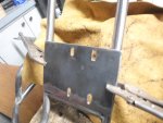
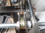
After lots & lots of clean up, I re-mounted the axle & brake assemblies
…aligned & tested the brake system
...covered & protected everything
…& then, got the brake pedal mounting bracket welded on :thumbsup:
 

Attachments

  • SAM_3190.JPG
    SAM_3190.JPG
    315.9 KB · Views: 1
  • SAM_3189.JPG
    SAM_3189.JPG
    313.5 KB · Views: 1
  • SAM_3186.JPG
    SAM_3186.JPG
    317.5 KB · Views: 1
  • SAM_3185.JPG
    SAM_3185.JPG
    311.3 KB · Views: 1
  • SAM_3182.JPG
    SAM_3182.JPG
    314.2 KB · Views: 1
  • SAM_3191.JPG
    SAM_3191.JPG
    316.6 KB · Views: 1
  • SAM_3193.JPG
    SAM_3193.JPG
    315.2 KB · Views: 1
  • SAM_3194.JPG
    SAM_3194.JPG
    318.1 KB · Views: 1
Top