Lawnmower engine build

Status
Not open for further replies.

ryf

New member
Messages
309
Reaction score
0
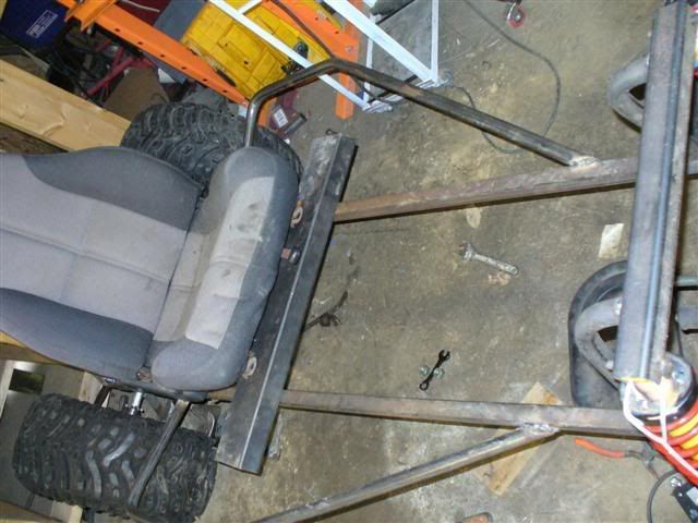
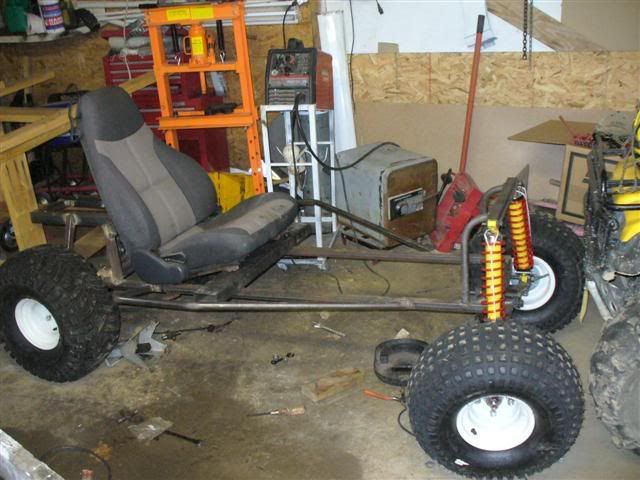
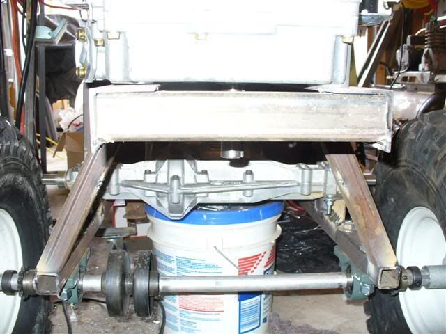
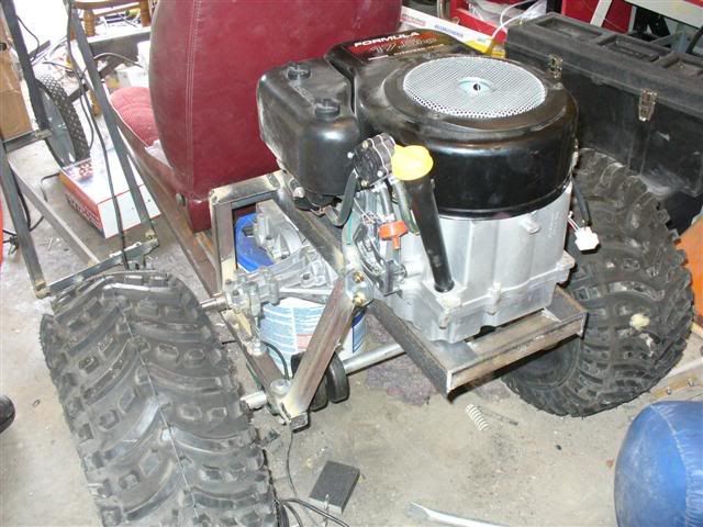
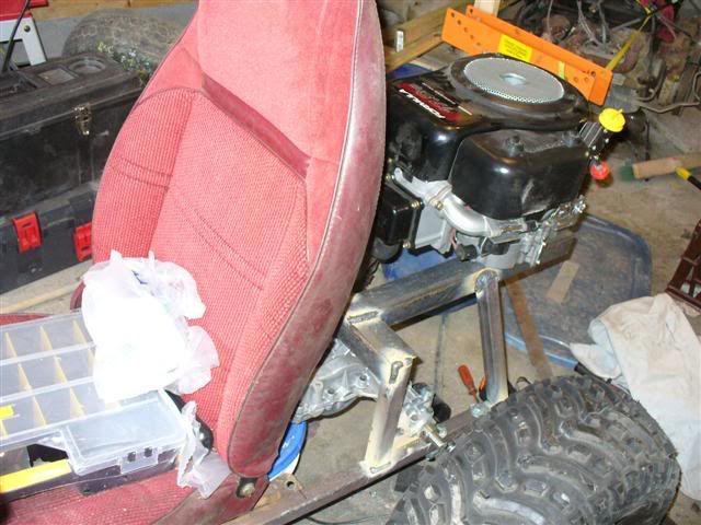
its drive system is made from mower parts, looking for all thoughts and opinions. it is not fully welded, but its got enough to get setup for a photo op! it will have a front suspension when finished, not pictered yet as it is nowhere near completion. that pickup seat is not the planned seat but it gives good effect. the brakes drums on the axle are for band brakes, they came with the axle, I will be using them for a parking type brake and an ford escort brake disc and caliper for normal braking.

pardon the mess, my garage has a cut up pickup hiding in there as well.


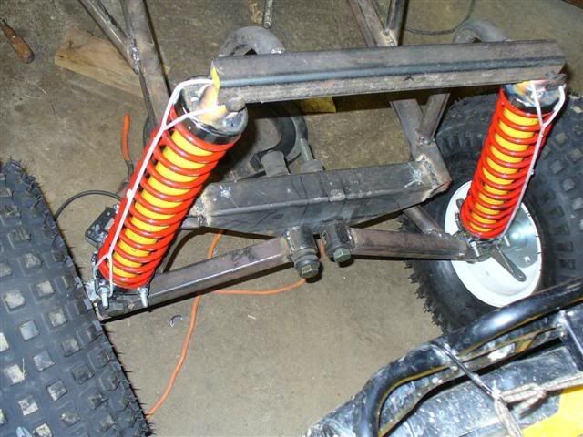
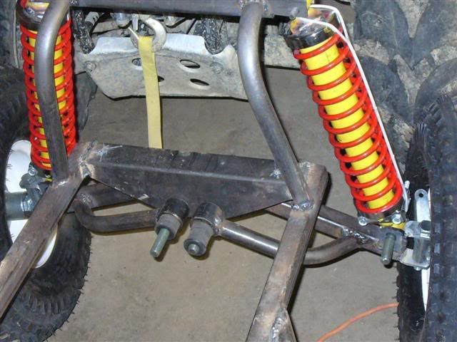
it will have tire protector framing in front of the rear tires (basically a triangle that pushes the cart off trees/rocks so you are less likely to bend the axle....the roll cage will tie in on them)
 
Last edited:

ryf

New member
Messages
309
Reaction score
0
posting without pics... stripped it back down to bare frame, got it the back fully welded up. front springs and bushings are coming this week. have to wait until I get paid as I need to get some more steel for the roll cage.
 

RobertD

Administrator
Staff member
Messages
3,019
Reaction score
56
Location
Texas
looks amazing! are those proper bearings on the back axle -- they look like it.
 

ryf

New member
Messages
309
Reaction score
0
posting without pics, should have some tommorow. Update as follows:

Moved over to a bigger emptier garage/workshop, and took my tools with me, its my father in laws place. got my front suspension and side protection bars mounted today, so will go back and get pics of pogress if I don't work on it anymore. only thing left is pedals & hand brake, steering, and bend out a roll bar. so we are only at the most a month away! woohoo...
 

ryf

New member
Messages
309
Reaction score
0
this is a shot of the axle and elbow protectors/ side guards... starting to look like something.


front and back shots of the shock mount area, it WILL be tied into a rollcage before its rolling, but can currently hold my weight bouncing on it (I'm a healthy 325lbs, so its safe enough) check out those hand made front a-arms!


the "far and away shot" there will be outdoor pics with more lighting later, but it was early when I got these. its sitting high in the front, keep in mind my weight, settling springs(most soften way up after a few rides), and adjusting later if needed, it'll be A-OK I think.


I have 17 new and better outdoor pics, my brother in law and I got it rigged up with a cross bar on the spindles (for moving it around, not for long term use) so we could get some better pictures outside. I'm not going to waste time or thread space posting them here... but I did put them on Photobucket for those who are enjoying the view! if you decide to check out the better pics, the tires on the back are not tight, so in some pics they will look crooked (finger tight cuz we take it all off to weld)


http://s129.photobucket.com/albums/p224/ryf_photos/atlma/
 

2or3wheels

New member
Messages
1,294
Reaction score
0
Location
Minneapolis Minnesota
Im fairly new to this so i may be wrong, but are your a arms going to touch the frame when they compress? it looks like they might in the pics but theyre pics and can be deciving. but anyways that thing looks mean and looks like its going to be a blast.
 

ryf

New member
Messages
309
Reaction score
0
in theory it could, but it will require a fair amount of compression (almost 5" at the tires center) I plan on putting a small bumpstop on there, but the likely hood of me compressing the springs that far is pretty unlikely due to the light front end, and the progressive nature of the spring/shock combo I'm running.
 

ryf

New member
Messages
309
Reaction score
0
ok just makinjg sure dont want to wreck it right away.

no doubt.. not much will get done this week. my parents are coming up for a visit. I have come up with a few good ideas...

as far as breaking things.... thats what balloon tires are to help guard against.
 

ryf

New member
Messages
309
Reaction score
0
ok... posting to keep you guys hooked.. should have pics tommorow, as of today I have a completed steering assembly! no brakes but we dragged it around the yard (with a 4 wheeler) to "test" the steering throw and cuz me and the brother in law wanted to. the seat is now permanently mounted, as well as a control box mounted on the steering wheel for ignition and switches.

lost a little time this week as I'm also working on redoing my kitchen... so time is dear right now.
 

robin

New member
Messages
584
Reaction score
0
Location
in a house
the teeth on one of your back wheels is rong way i think looks sweet kinda like waht ime tring to make but not getting far as sourcing parts is a pain in the neck
 

AdrianH

New member
Messages
12
Reaction score
0
Location
North West UK
I am puzzled, looking at the front of the kart at the suspension and steering set up.

What are you using to transfer steering from the column to the front wheels?

I saw one picture with a rigid bar, but I have assumed that was for the sake of the picture to keep the wheels straight.

I am guessing that you will have some form of steering rack that will allow the rise and fall of the wheels with the suspension system. Can you let me know your plans and sorry if this is being cheeky but looking for ideas and wondering about what to use with a double A set-up for my next project!

Cheers

Adrian
 

ryf

New member
Messages
309
Reaction score
0
the first pic is the front end, sorry its dark. I'm using the simplest sort of steering, a pivot bar and end links. I set the end links pivot approximately the same distance from the a-arm as the turning bar on the spindle, that simple. a tip here is to keep the pivot bar from shaft to where the tie rods hook in as short as will allow full articulation of the wheels, this keeps the wheel as precise as possible (more movent at the wheel for the same tire articulation), as well as giving the most leverage if your going with big fronts... if you make it long, it will be scary twitchy (we tried it, it was hard to turn safely) so in short, figure out a way to have a tie rod section as close to exactly the same length as the a-arms it will do what you want.

it follows and toe change is minimal, on dirt perfection is a waste of energy since you have a solid rear axle that makes turning a pain. anyway I used a piece of an escort steering column to run a pivot under the a-arm, and the u-joint from same to run it up to the "trimmed" escort wheel welded straight to a piece of 3/4" pipe, and a 5/8" rod was ground to fit the u-joint.

if you want to use a rack and pinion, they are costly so takes pics for the rest of us to drool over. and you will probably wont get the lengths to match with an out of the box rack kit, so it wont match the A-arms pivot (thats why I went this way, paying all that money for crappy steering IMO seemed stupid) if your lost, I'll try and take pics tommorow when its bright out again... best I can offer, no plans were made in the building of my cart, I just had a vision and made it.
---- edit here----

I chopped and brightened it up, its easier to see the tie rods are very close to parrallel to the a-rm, you can see the dark a-arms under the shiny tie rod.

 
Last edited:

AdrianH

New member
Messages
12
Reaction score
0
Location
North West UK
Yes I see the steering links now!. I thought I was looking at part of the swinging arm previously, hence the question.

Thanks for that.

Adrian
 

ryf

New member
Messages
309
Reaction score
0
just a teaser for this weekend, I have my drive chains, plan on more welding on the supports and etc. photos of course.
 

ryf

New member
Messages
309
Reaction score
0
its 1 1/4 for the square tube and 3/4" pipe for round tube, that ends up around 1 1/8 for the round tube.

I realized I haven't posted the tire size, they are 23" rears, 22" fronts I'm working out a hydraulic brake system, since I have alot of relevant parts already. hope that helps put it to scale.
 

loinvein

New member
Messages
5
Reaction score
0
is there going to be two chains one on each side of the axle coming from the transmission. or do the same amount of power come from both sides of the transmission. i am new to build go karts and am trying to see all the diffrent designs out there. i hope i dont bother you with my questions.
 

dirtynelson

New member
Messages
10
Reaction score
0
was that engine off a riding lawnmower? if so did you remove the govenor and if u did how did you accomplish that? if not did u do something else?
 
Status
Not open for further replies.
Top